


Contributing Writer
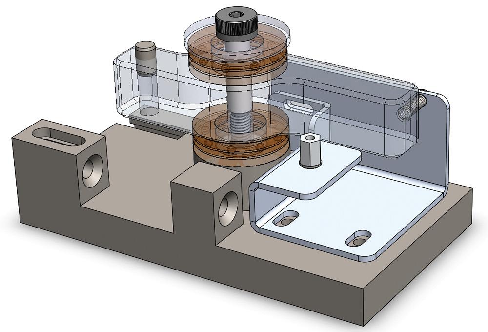
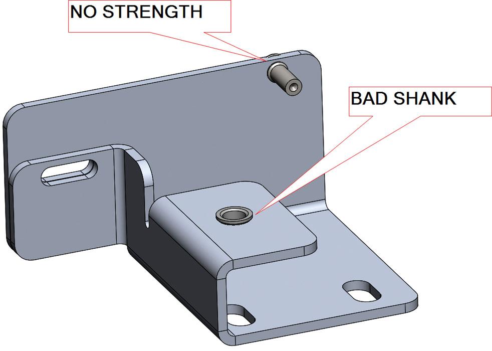
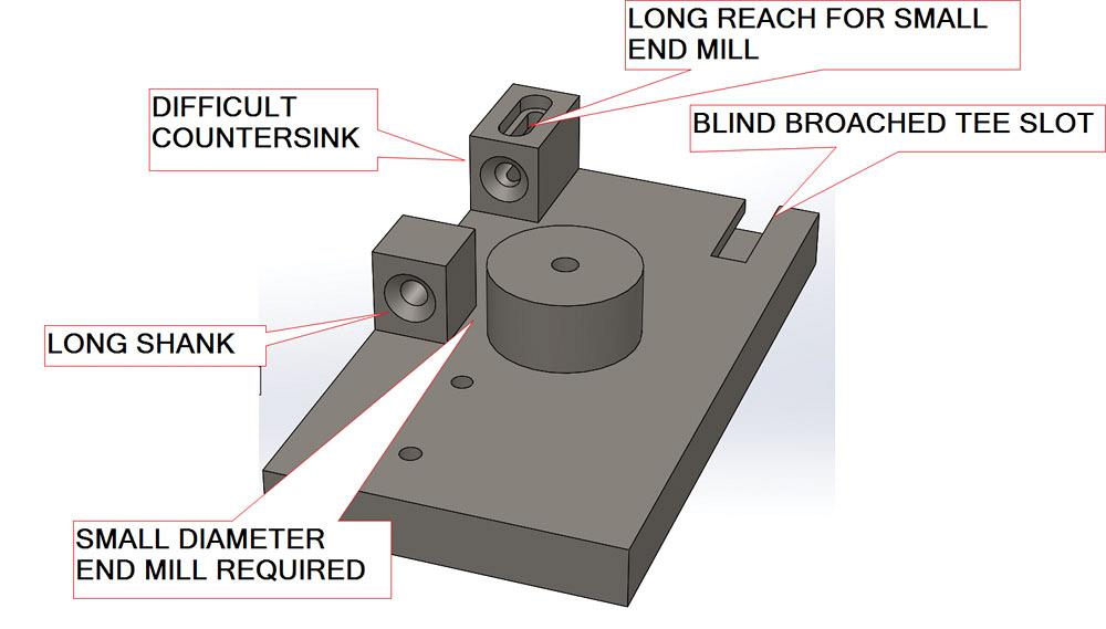
Figure 1
This model satisfies many mechanical goals in terms of
motion, but it fails when it comes to being buildable.
How many problems do you see?
“How many of your staff members are dedicated to DFM, design for manufacturability?”
“Not many. Most are against it.”
Hopefully, this dialogue about DFM struck you as a joke. While you’re in a good mood, please take a test. Study Figure 1. The challenge is to spot the problems in the design. (Hint: There are more than a few.)
For example, the spring’s inside diameter is too small for the pin it is pressed onto. That is probably an unfair test question because the illustration makes close examination of this model difficult.
A more obvious problem is with the countersunk holes. One of them requires a very long shank on the countersink tool. The other requires an exotic, far-side countersinking whip or fabricating the part with some process other than milling.
As we dig through this atrocious example of design, we do so with a kind heart and in a helpful spirit. The pressures that led to this design stage must have been compelling. We do not seek to impugn the capability of the originator of the concept model.
Now is the time to transform a concept piece into a virtual prototype suitable for fabrication. We bring practical fabrication skills to merge with the vision for the product’s function.
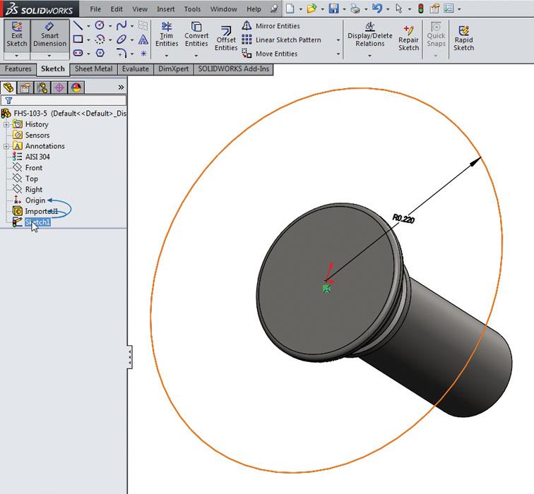
Figure 2a isolates a dowel and a lever. We have learned from our design goals that the dowel is supposed to press-fit into the hole. Interference Detection is a handy CAD tool to verify this.
The dowel and the lever have been selected in the Interference Detection Property Manager, shown to the left of the graphics window in Figure 2a. At the middle left, we see alarming results: There is no interference between the dowel and the lever. The dowel will fall out of the hole.
A solution is shown in Figure 2b. The lever is being edited, and we see the Hole Wizard Property Manager. The hole for the dowel has been changed from a drilled hole to a dowel hole. All the designer needs to do is select the type of fit. In this case, the designer selects Press for fit with a 5-mm dowel.
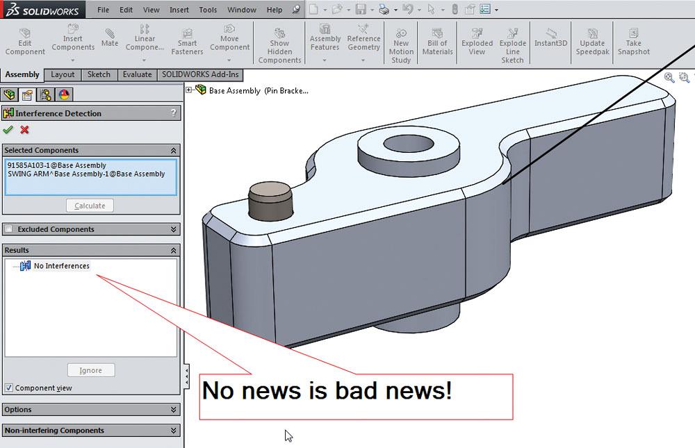
Figure 2a
Figure 2a
The Interference Detection tool can be used to verify
how a dowel fits into a hole. In this case, no interference
means no press-fit.
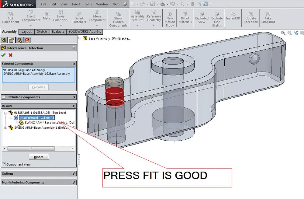
The result is shown in Figure 2c. Again, the Interference Detection is set to check the dowel and the lever. We are pleased to see that the dowel will stick in the hole.
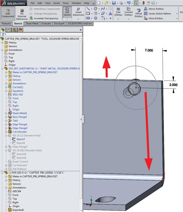
Figure 3a shows the sheet metal bracket with captive hardware. Folks in the sheet metal trade will note at a glance that the stud is too close to the edge of the part. Perhaps more difficult to discover is the shank length of the captive nut. For this gauge of sheet metal, a shorter shank would be better. Editing the model to comply with the hardware manufacturer’s recommendation for sheet thickness and distance-to-edge corrects such design flaws.
To goof-proof the captive hardware, one trick is shown in Figure 3b. In this example, a circle was sketched in the model to represent the minimum distance center-to-edge of sheet metal. The value of the sketched radius was determined by looking up the manufacturer’s recommendation.
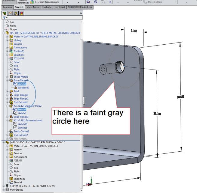
Returning to the sheet metal, we see in Figure 3c how the fastener was located. The good news is that we see the reference circle showing the goal of minimum distance to edge. The bad news is that the dimension to the center of the hole is from the edge of the sheet metal. If we change it now, the hole will move relative to the sheet metal bend. That’s not our goal.
To correct this, we change the dimension so it references the bend, then we change the sheet metal to surround the fastener’s hole correctly. The results are shown in Figure 3d. The center of the hole is controlled to match the location of the lever, and the edge of the sheet metal has been moved to extend at least to the reference sketch in the captive hardware.
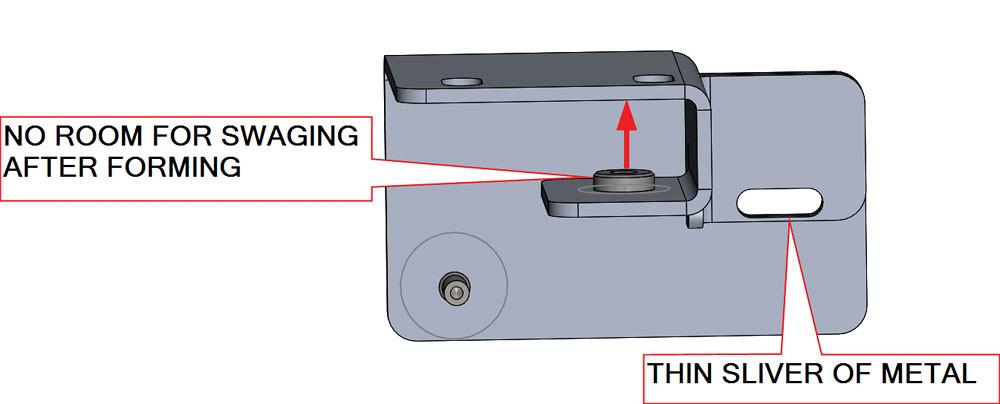
How bad can one piece of sheet metal be? The captive nut shown in Figure 4a is hard to reach with tooling for swaging. It may need to be installed before the sheet metal is bent.
Also in Figure 4a we note a slot that appears to be very close to the edge of the sheet metal. This can be done, but probably requires laser cutting instead of stamping.
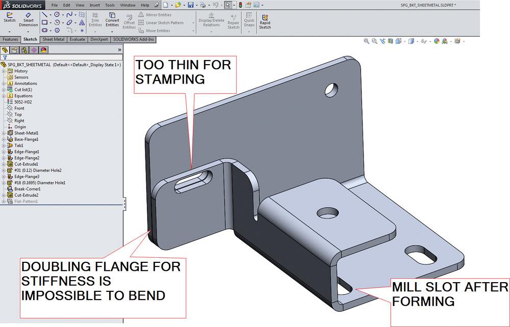
As optimizers for fabrication, all we can do at this stage is note some cost drivers in this component. Let’s give the sheet metal part a closer look.
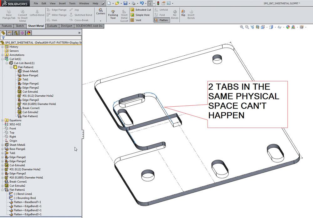
Figures 4b and 4c reveal a substantial problem with the design. The slot cutout passes through two sheet metal flanges. Only one of those flanges can exist unless this part is welded or 3-D printed. As shown in Figure 4c, this design will not unfold because two tabs intersect.
(CAD hint: Using CAD to test the unfold/fold of the sheet metal model is an important part of DFM.)
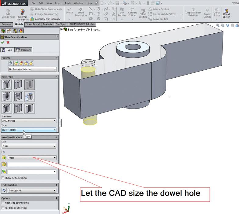
Figure 2b
If the CAD can do the work, let it! In this case, a wizard
can be used for setting the hole size based on the kind of
fit desired. Press-fit is our goal.
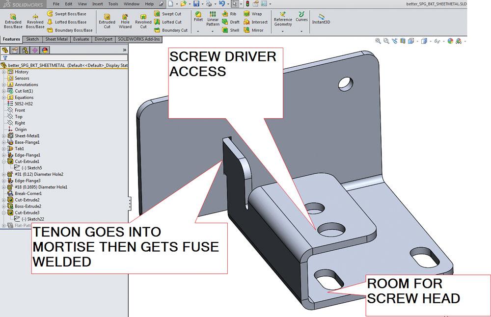
Figure 4d shows an improved version of the bracket. The impossible tab has been replaced with a mortise and tenon for welding.(CAD hint: Aficionados of the brand of CAD being used here might appreciate the nuances of the tenon. To keep the sheet metal from intersecting itself, the mortise gets cut first, and then the extrude for the tenon passes into the mortise.) This meets the design goal of stiffness. It turns out that the nasty slot was intended for a stiffening fastener and will no longer be needed.
Figure 4d also shows the relocation of mounting slots away from the bend. This gives the screw head a chance to sit flat. For that same screw, we’ve added a hole so a screw driver can get to the screw head.
The point of this sheet metal exercise is to demonstrate the designer’s need for a combination of 3-D modeling skills and an awareness of constraints of tooling and assembly. With more time and authority, one might improve this further by making more room for swaging the nut into the sheet metal, but that involves changes to the lever and bearings.
The base frame for this mechanism is shown in Figure 5a with a variety of easy-to-spot problems. The countersink access issue has been noted previously. The T-slot is modeled with square ends, which should change to allow a spinning cutter to carve the blind slot. For an experienced machinist, these problems are obvious. For someone who has never cleaned oily chips out of a sump, these considerations seem hard to assimilate.
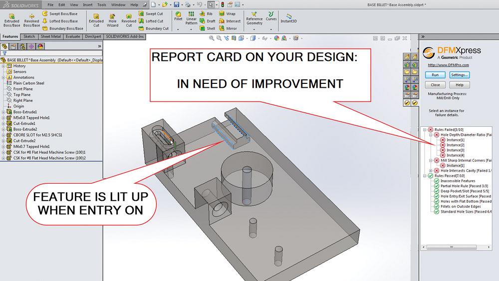
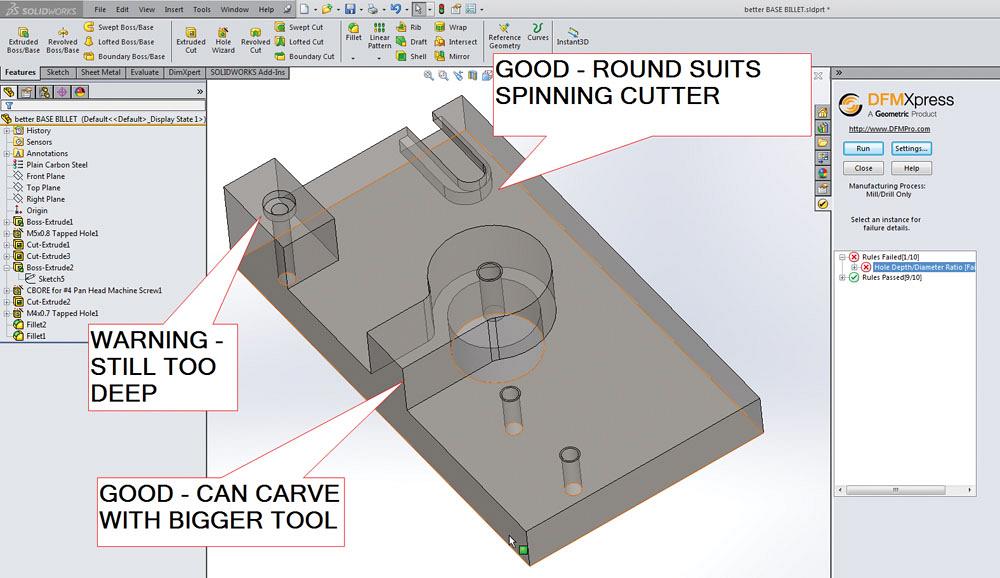
Figure 5b shows a report generated by the CAD software that automatically identifies design features that violate best practices in machining. This same tool works with sheet metal too. After appropriate edits to the design, fewer “violations” are encountered as shown in Figure 5c. Some red warnings remain, but they have to do with the depth of holes as a ratio to their diameter.
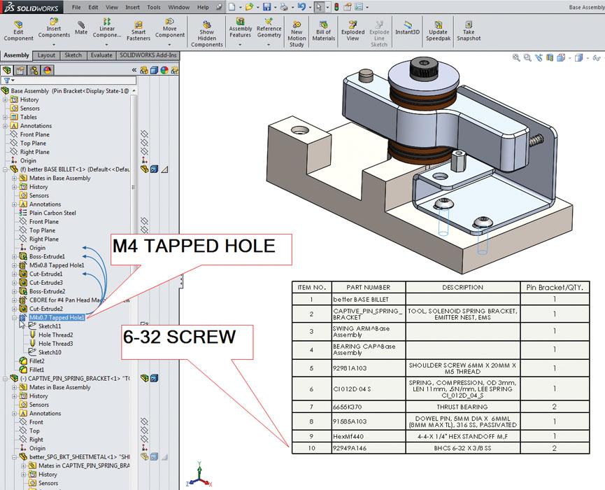
The bill of materials table is often used in the process of procuring items for the assembly. The BOM table can be used as a design checker too. In Figure 6 we see that a 6-32 screw is being installed in an M4 tapped hole. As with the incorrect shank length on the captive nut, the solution is to change either the fastener or the part it is going into.
It is good to catch these problems now, before the project commits to raw material. By using a combination of tools for visualization, measurement, and detection, we’ve moved this design from concept stage to almost ready for fabrication. What more could be needed?
Gerald would love to have you send him your comments and questions. You are not alone, and the problems you face often are shared by others. Share the grief, and perhaps we will all share in the joy of finding answers. Please send your questions and comments to dand@thefabricator.com.


The Fabricator is North America's leading magazine for the metal forming and fabricating industry. The magazine delivers the news, technical articles, and case histories that enable fabricators to do their jobs more efficiently. The Fabricator has served the industry since 1970.
start your free subscription
Easily access valuable industry resources now with full access to the digital edition of The Fabricator.

Easily access valuable industry resources now with full access to the digital edition of The Welder.

Easily access valuable industry resources now with full access to the digital edition of The Tube and Pipe Journal.

Easily access valuable industry resources now with full access to the digital edition of The Fabricator en Español.
In this episode of The Fabricator Podcast, Caleb Chamberlain, co-founder and CEO of OSH Cut, discusses his company’s...


