


Contributing Writer
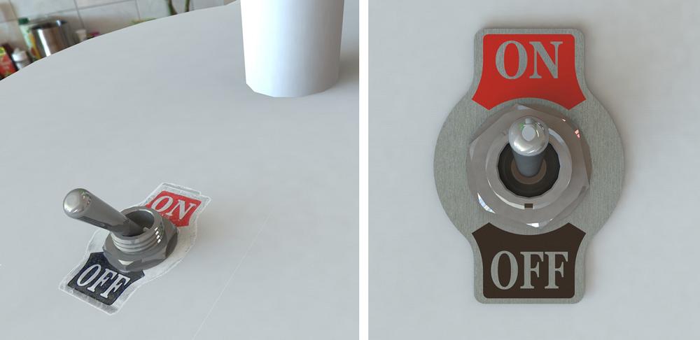
Figure 1
The on/off label was modeled by using a graphic image file (JPG) as a decal. (left) This method is good for visualization but does not help with the bill of materials or with fabrication.
Figure 2
The on/off label in this image (right) is an assembly of a sheet metal part and two pieces of epoxy ink. The BOM will be good, but this image is not useful for manufacturing—too much clutter. All that is needed for screen print setup are the red and black areas.
If the primary goal of the CAD model is visualization and not manufacturing, then details such as legends-by-the-knobs and logos-for-show might best be modeled by using a “decal.”
Some 3-D CAD software can import any of several graphic file formats for this purpose. Controls in the CAD allow the image to be stretched and manipulated to achieve nice-looking results. Figure 1 shows an assembly with a picture of an on/off label rather than a model of the on/off label. This might be considered to be a time-saving trick.
Whereas the decal might be good for visualization, the CAD-generated image is useful only for a limited range of fabricating processes, such as etching. For engraving, the constraint is a lack of physical features that can be measured and directly translated into machine control commands.
If screen printing rather than engraving is your goal, you need a graphic file with high contrast and sharp focus. Even a nicely rendered CAD image such as Figure 2 would require a significant amount of photo processing to achieve a useful image for screen printing setup. The red and black areas are all that are of interest.
For purposes of inventory management, you might find it useful to have the part number and revision emblazoned upon the item. If “mark the part” is the only design guide, the CAD jockey may not need to model the part marking at all. A simple note on the production drawing could serve to get the marking done.
However, with no specification to control the part marking, the results are haphazard. Some production batches could have ink- or metal-stamped part markings; others could be screen printed. There is likely to be variety in the location of the marking from part to part.
As the design of the product is refined, the location, font, and content of the part marking are likely to require specification to eliminate surprises. Figure 3 shows a production drawing with appropriate notes for marking.
To speed this modeling effort, the CAD jockey can use a Library Feature to drag and drop a part marking feature onto a face of the model. (See “3-D CAD: Part marking matters,” Precision Matters, The FABRICATOR, December 2012, p. 50 for a step-by-step discussion of this topic.)
If the part marking is represented as a feature in the 3-D model, it will appear on all of the production drawings. Exploded views as shown in Figure 3 are easy to create. The part marking information is also present in the STEP files CAD generates for the benefit of CNC programming. It is up to the CNC programmer to convert the part marking specification into a manufacturing process. Some of the conversions that may need to take place include finding the centerpoint for the metal stamp tool, creating commands for laser etching, or setting up a tool path for engraving.
Including part marking as a routine part of product design is not difficult. It has surprising benefits as well. Visualizing the part marking in CAD helps prevent unintended consequences in the early production runs. Sometimes it matters how the part marking is oriented. CAD is all about getting it right before committing to raw material.
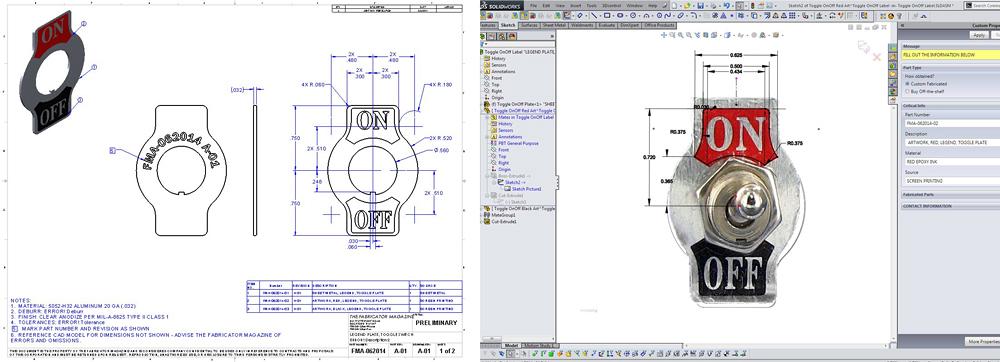
Figure 3
See note No. 5 on the drawing (left). It is specifying how the part is to be marked for inventory control.
Figure 4
This screen shot shows a sketch in progress (right). A picture of a label was downloaded from the Internet and used as a Sketch Picture to guide the placement of the line segments in the sketch.
We are making a slight distinction between part marking and legends. In Figure 3 the legends are shown in red and black, whereas the part marking on the back side does not have any color requirement.
A drag-and-drop method works well for modeling part markings. They almost always have the same set of data—for example, part number and revision—and are relatively consistent for a family of products. The modeling of legends and logos is not as well-suited to drag-and-drop work flow.
Legends are directly associated with a feature and function. They exist primarily for the benefit of the end user—something like “On” next to the power switch. Legends have style and express inspiration that is consistent with the product design; part markings comply with standards.
Legends frequently appear in many locations, perhaps in many fonts and colors. For that reason, screen printing is a popular manufacturing option for legends and logos.
As a part of the screen printing process, the CAD jockey contributes primarily to the preparation of the screen mesh masking. As mentioned earlier, the setup for screen printing requires one or more high-resolution black and white images. Such a masking image will be used by the screen printing setup crew to produce a master mask on clear acetate sheet plastic with the masked areas blocked out with opaque ink.
This master mask is used as an optic filter while curing the photo-resist filler that is applied to the wire mesh screen. After the filler is cured, the screen is rinsed to wash away the uncured filler. The resulting areas with bare screen mesh will allow the screen printed ink to pass through onto the target part.
Several CAD modeling methods that can produce the needed image for screen printing setup are available. One approach is to model the legends and logos to mimic the physical world—that is, extrude each letter in 3-D space. Those extruded bodies are then assembled with other components to create a faithful visualization of the design.
With the features to be screen printed contained in a separate CAD file, the production of an image for screen printing is simply a matter of rendering that CAD file into the graphic file format the screen printing crew desires.
One possible workflow in 3-D CAD is to create a multibody part file. This file contains all of the legends that have a common color and common surface. If multiple colors or multiple surfaces are involved, additional masking files will be needed.
Extruding text to create solid bodies in 3-D CAD involves entering data, selecting suitable fonts, and setting their sizes. Unlike text for part markings or legends, logos don’t rely entirely on premade fonts. Logos are similar to legends in terms of being bodies in a 3-D CAD file, but the profile of the logo is modeled by sketched line segments.
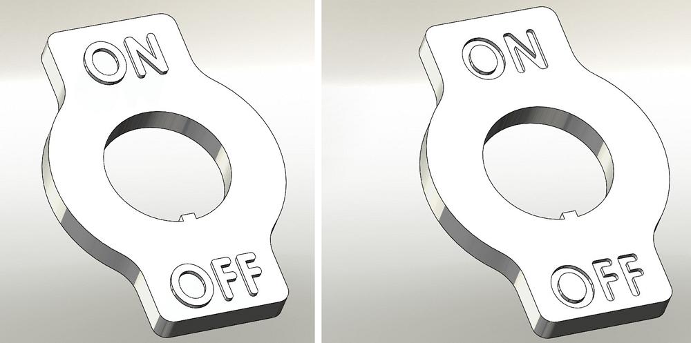
Figure 5
When carving the molding tool for this part (on left), the milling of the lettering is completed after the main part of the mold is polished.
The tooling for this part will be harder to machine and harder to polish.
However, this lettering could be paint-filled, whereas the lettering in Figure 5a (left) cannot. If speed and low cost are the drivers, then 5a is a better method of manufacture. Figure 5b (right) shows an embossed engraving that is harder to tool.
For free-hand modeling, the use of a Sketch Picture of the desired logo as a background while drawing is relatively efficient. Figure 4 shows a sketch with a Sketch Picture that was used to model the red background for “On.” The next modeling step in this example was to Sketch Text in order to cut the word “On” out of the red zone. In some cases, the software can trace edges in the logo image to automatically produce a usable sketch.
The CAD jockey should keep in mind that, as a process, screen printing has physical limitations. It prefers relatively flat surfaces. The screen mesh is mounted in a rigid frame, and that frame may restrict access to the target part.
In addition to offering a variety of colors, screen printing can have fine resolution. Depending on the ink viscosity, the points on arrows and sharp corners can be pretty high-resolution with just a small radius. Mechanical engraving, on the other hand, requires much larger radii.
Engraving beats screen printing when it comes to durability. It is also practical to engrave on curved surfaces that are not suitable for screen printing.
Laser engraving is similar to milled engraving. The difference is in the “bit”—the engraving bit being either a rotating cutter or a beam of light.
Of course, the downside of mechanical engraving is speed when compared to screen printing. Laser engraving is relatively speedy, offers very high resolution, and requires less mechanical preparation and setup than screen printing. As with screen printing, the CAD jockey’s deliverable is a graphic image file.
When the highest resolution is required, EDM engraving is an option. The production of the tool for EDM represents a significant expense and the process is not quick. EDM can be efficient when it is compared to the manufacture of mold tooling.
For products designed for an injection molding process, tool- and diemakers have some recommendations when it comes to engraved lettering. Little details have a big impact on what it takes to carve the mold. First, avoid tiny and deep pockets that are hard to fill with plastic. Each facet of each letter must be machined and polished in the cavity of the mold. Second, project the lettering out from the face of the finished part (see Figure 5a). This allows the main cavity of the mold to be carved and polished prior to carving the lettering into that otherwise completed part of the mold. Figure 5b shows the projection in the other direction—into the finished part instead of away from it. The floor of the mold must be carved away to reveal the lettering in reverse. Obviously, this is a slower machining and polishing process than simple line engraving.
When modeling text that will be mechanically engraved, the CAD jockey and the CNC programmer have slightly conflicting needs. The 3-D model is to be a faithful representation of the finished product. The CNC programmer would prefer to have the tool path for the engraving rather than the finished look. Not many fonts satisfy both needs.
It would be laborious to model text as Swept Tool Cuts, but the result would be visually correct and relatively easy to process through CNC programming. It is much speedier for the CAD jockey to use commonly installed fonts for creating the profile of the legends. Using such fonts, the 3-D CAD model will not have ideal centerline tool path-driven engraving.
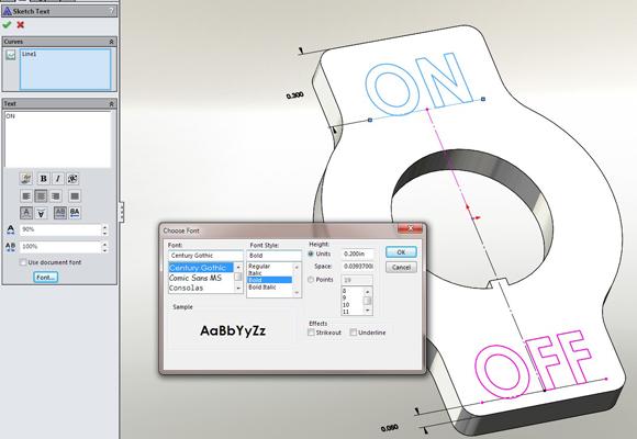
Figure 6
After the legends were modeled with Century Gothic font, fillets were added to allow larger-diameter engraving bits to be used. This example shows lettering that could be carved with a 1⁄32-in.-diameter mill, which would result in a very slow machining process.
The prudent font selection is one with parallel strokes and with minimum serif—Century Gothic, for example. This at least minimizes the number of tool paths for engraving. To improve the model for manufacturing, fillet the ends of each stroke to represent the radius left by the rotating cutter. Figure 6 is a screen shot of the setup for Figures 5a and 5b. Font sizes of 20 points and bigger generally result in text that can be engraved with a rotating cutter bit. The smaller the font, the more time it will take to engrave.
Gerald would love to have you send him your comments and questions. You are not alone, and the problems you face often are shared by others. Share the grief, and perhaps we will all share in the joy of finding answers. Please send your questions and comments to dand@thefabricator.com.


The Fabricator is North America's leading magazine for the metal forming and fabricating industry. The magazine delivers the news, technical articles, and case histories that enable fabricators to do their jobs more efficiently. The Fabricator has served the industry since 1970.
start your free subscription
Easily access valuable industry resources now with full access to the digital edition of The Fabricator.

Easily access valuable industry resources now with full access to the digital edition of The Welder.

Easily access valuable industry resources now with full access to the digital edition of The Tube and Pipe Journal.

Easily access valuable industry resources now with full access to the digital edition of The Fabricator en Español.
In this episode of The Fabricator Podcast, Caleb Chamberlain, co-founder and CEO of OSH Cut, discusses his company’s...


