


Contributing Writer
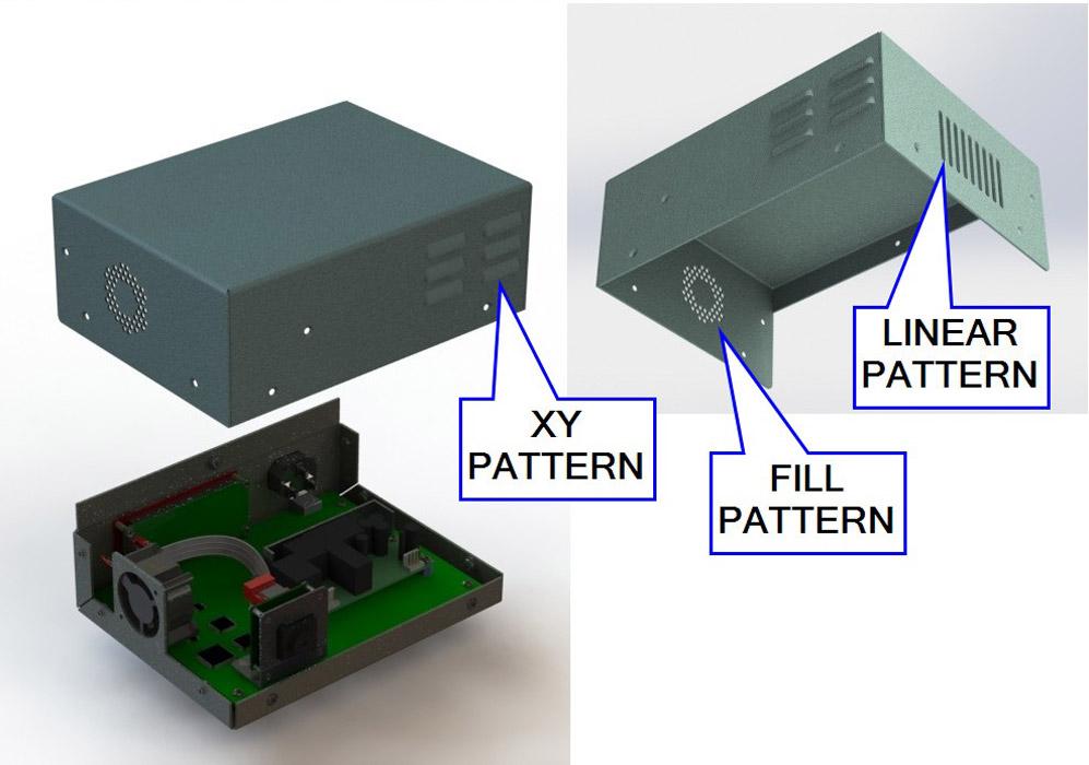
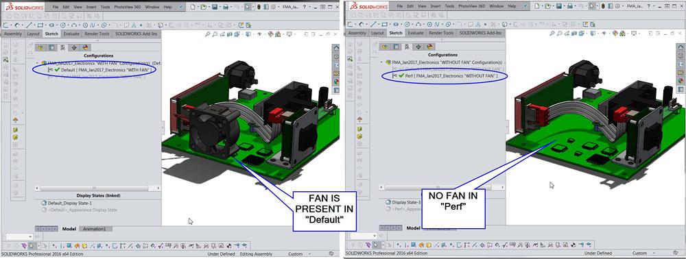
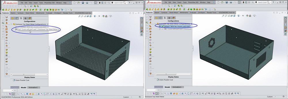
Figure 1
This is the Default starting configuration of an imaginary product. The CAD task is to switch quickly between this version and another version of the product that does not have the fan and also has a very different vent pattern.
Editor's Note: If you would like to download the 3-D CAD files associated with this column, click here.
The phantasm shown in Figure 1 returns as a star model for this edition. The cover is shown out of position for convenience of emphasis. The evolution of this model, spanning years of sporadic revision, is similar to that of a real product. The resulting design has a variety of vent patterns that are strictly functional.
In the theme of real-world model evolution, the task at hand is to create a version of this product that does not have the fan, the louvers, or the vent slots. We want to create a pattern of holes in the cover for convection venting.
Here’s a CAD tip: A product’s variations can be represented with configurations.
Figure 2 reveals a trick behind the CAD tip: Instantly propagate a new configuration to the affected models in the assembly. It’s easy as 1-2-3:
The check box settings shown in Figure 2 cause the Perf configuration (along with the optional descriptive information) to be created in several places. In this example, the check box settings match the goals of changing the electronics module to remove the fan, updating the cover to change the venting, and altering the chassis to remove the fan mounting.
After creating the new configurations in the children components, the CAD work flow is to edit those children components to actually reflect the design goals within those configurations. As a starting point, the issue of removing the fan from one version or configuration of the model is considered.
Figure 3 shows a comparison of the electronics module’s configurations. To prepare for this illustration, we selected the Perf configuration, and the fan was suppressed. That’s it as far as CAD editing goes. The right view shows the new Perf configuration. The fan has been suppressed. The left view shows the Default configuration; the fan is unsuppressed.
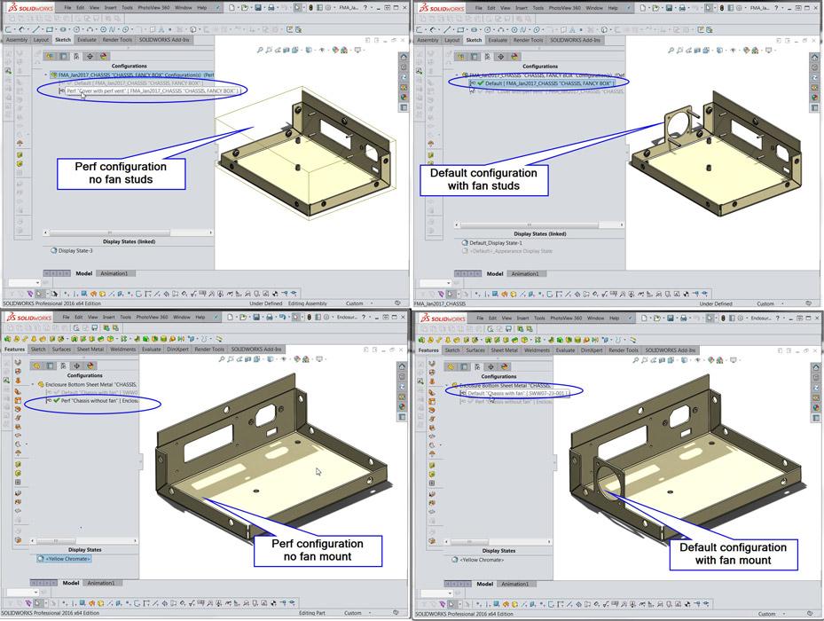
Next in this CAD work flow example are changes to the chassis. Note that the chassis is an assembly of sheet metal and captive hardware. The assembly and the component sheet metal are configured. Figure 4 shows a comparison with the fan and without the fan for both the chassis assembly and the chassis sheet metal.
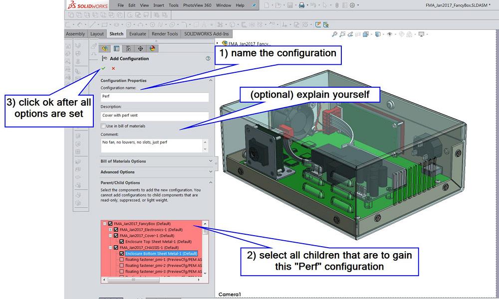
Figure 2
The CAD work flow starts by adding a configuration to the top-level assembly and adding that same configuration to the children components.
The final component to update is the cover. Figure 5 compares the difference between the new Perf configuration and the Default configuration that has the fan hole, louver array, and vent slots.
CAD notes: The Perf configuration in the cover part suppresses the louvers, slots, and fan pattern. It then unfolds the sheet metal and uses a boundary sketch for a fill pattern of 5⁄32-in.-diameter holes on 9⁄32-in. staggered centers. The part is then refolded for a realistic result.
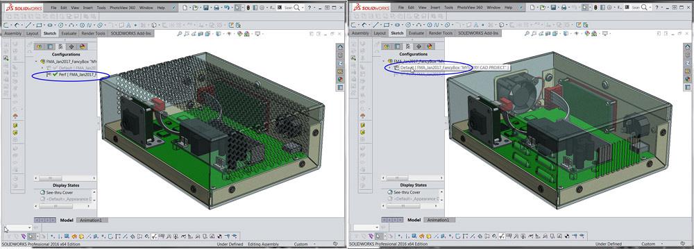
The CAD work flow concludes with a return to the top-level assembly (see Figure 6). When the assembly is in the Perf configuration, the child components are also in their respective Perf configurations. The left view in Figure 6 shows the perforated cover, the no-fan chassis, and the no-fan electronics module. The right view shows the default configurations for these items. The goal of being able to switch between versions of the product with the selection of a configuration has been satisfied.
The Perf is a palimpsest of the Default. Traces of the original configuration remain in the new configuration. During product development, it may be useful to be able to switch quickly between sometimes radically different versions of the invention. When the design matures and is ready for manufacturing, the configurations can be eliminated by using separate file names for component models. This change in modeling technique is generally beneficial to long-term revision control of models.
Gerald would love to have you send him your comments and questions. You are not alone, and the problems you face often are shared by others. Share the grief, and perhaps we will all share in the joy of finding answers. Please send your questions and comments to dand@thefabricator.com.


The Fabricator is North America's leading magazine for the metal forming and fabricating industry. The magazine delivers the news, technical articles, and case histories that enable fabricators to do their jobs more efficiently. The Fabricator has served the industry since 1970.
start your free subscription
Easily access valuable industry resources now with full access to the digital edition of The Fabricator.

Easily access valuable industry resources now with full access to the digital edition of The Welder.

Easily access valuable industry resources now with full access to the digital edition of The Tube and Pipe Journal.

Easily access valuable industry resources now with full access to the digital edition of The Fabricator en Español.
In this episode of The Fabricator Podcast, Caleb Chamberlain, co-founder and CEO of OSH Cut, discusses his company’s...


