


Contributing Writer
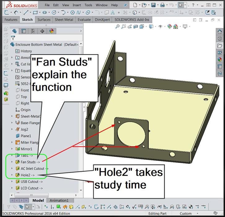
Figure 1
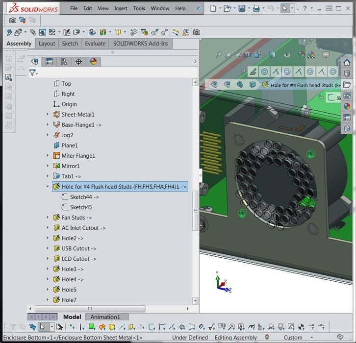
Names matter. It is recommended that features be renamed to explain the intent behind the design.
Editor's Note: If you would like to download the 3-D CAD files associated with this column, click here.
When it comes to product development, a “good” CAD model speeds the process. A “bad” CAD model takes too long to create and is difficult to modify.
Good CAD is self-documenting, speedy, and attuned to the fabrication process. That’s what we’ll focus on.
During product development, labor is expended to invent and create new models, as well as to revise the design and function—sometimes quite significantly. Adding detailed comments to CAD features at this stage is a distraction from inspiration.
However, as the development stage progresses, it is good to at least rename features. Figure 1 is an example of how the name of a feature in the history list can help the reviewer to understand the design intent behind the CAD modeling tools used.
When the product design matures, CAD labor is spent optimizing the model for cost and speed of fabrication. The CAD techniques the developer uses leave a forensic trail of how the model came to be. To the extent that that modeling trail is easy to follow, the CAD model will require less time to refine.
That’s good CAD modeling. Adding comments in the CAD at the final stage of development helps with understanding the design intent in the future.
The design history that is automatically embedded in the CAD model is the self-documenting characteristic of CAD that the product developer can take advantage of.
The Fan Holes feature shown in Figure 1 was created with the Hole Wizard and then renamed by the CAD jockey. Figure 2a shows the Hole Wizard setup used to create the feature, a Legacy Hole with an entered diameter value. Presumably, the diameter is suitable for the fastener that will go into it.
The good news is that the Hole Wizard creates a pattern of holes that is easy to populate with models of PEM® hardware. The moderate news is that the feature required renaming to give it intuitive meaning.
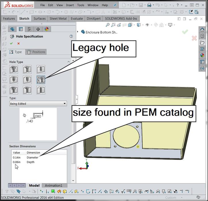
Figure 2a
The Hole Wizard is used to create a pattern of legacy holes with a specific diameter. We hope the hole size matches the PEM stud that will be swaged into it.
Figure 2b shows an alternative modeling technique. Instead of using a Legacy Hole, select what the hole is for; in this example, a PEM fastener. The drop-down lists allow selection of the type of PEM fastener as well as the size of the fastener.
Figure 2c shows the result in the Feature Manager’s history list. The feature’s name—Hole for #4 Flush Head Studs…—was created by the Hole Wizard and conveys some design intent without extra effort on the part of the CAD jockey.
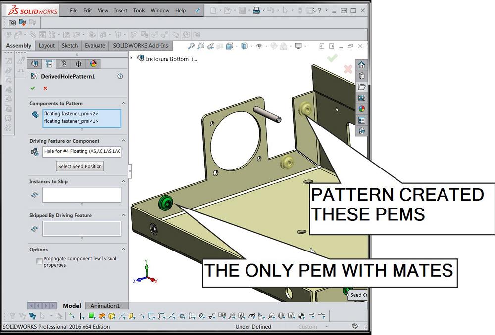
Figure 3 is a demonstration of using the pattern the Hole Wizard created to make patterns of fasteners (such as nuts and bolts). Note that the name of the pattern helps to verify that the correct pattern is in use and that the pattern is correctly sized.
As an example of speedy CAD, only one of the three PEMs shown in Figure 3 has mates to the sheet metal—a somewhat tedious task. The other PEMs are instantly positioned, effectively created without effort, according to the pattern. When the pattern is edited, the locations and quantity of patterned components update automatically.
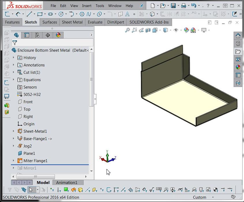
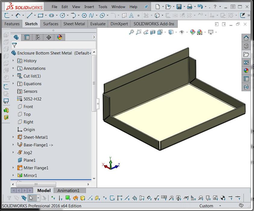
Figures 4a and 4b demonstrate the use of mirrored features for speedy CAD. In this sheet metal example, the flange and corner details on one side of the chassis can be worked out in detail, then instantly mirrored to complete the design. This also conveys design intent: Both sides of the chassis are to resemble each other.
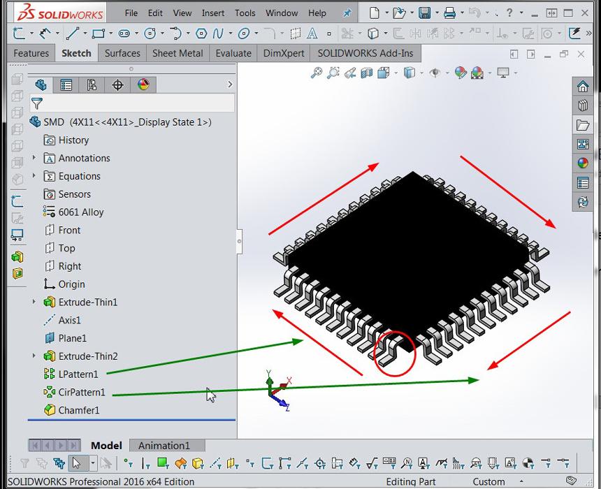
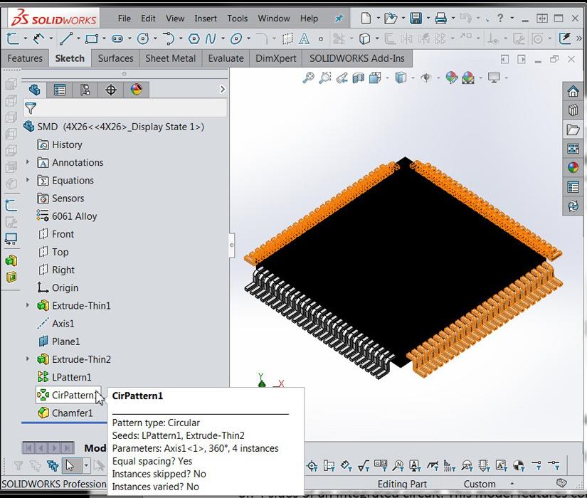
Figure 4c demonstrates the use of patterns for speedy CAD. In this example, a circular pattern of a linear pattern of a single leg is used to create the legs on four sides of an integrated circuit. This model features configurations; the configurations control the number of instances of the patterns. Figure 4d is a different configuration of the same model shown in Figure 4c.
Figure 5 presents the dilemma of detail. The fan blades are perfectly modeled and can be made to rotate under mouse drag. Perhaps that level of detail is important to visualization or to the design of the parts that are to be custom-fabricated. If not, then excessive detail, such as legs on the integrated circuit chips, is an example of slow and bad CAD.
In the realm of self-documenting features, sheet metal CAD tools are excellent. Their purpose is self-explanatory. They convey design intent and are easy to edit as the model matures.
It is possible, and sometimes advantageous, to create models of sheet metal parts with minimal use of sheet metal CAD tools, a sterling example being the Convert to Sheet Metal tool. With emphasis on self-documenting and easy-to-edit CAD, the use of sheet metal features from the get-go is recommended.
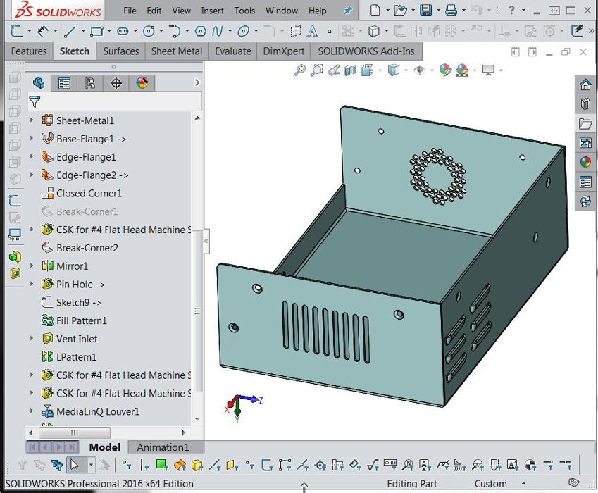
Figure 6 shows the design history of a sheet metal part. It started out as a base flange. Then, among other things, grew some edge flanges, tightened up the corner gaps, got mirrored, found some countersunk holes, sprouted a vent pattern, and popped out a pattern of louvers.
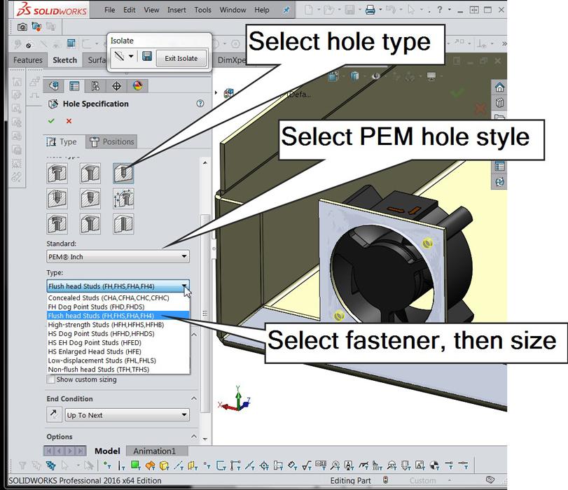
Figure 2b
The Hole Wizard has options that are ideal for many types of fasteners. Use of these options in the Wizard helps to create self-documenting CAD.
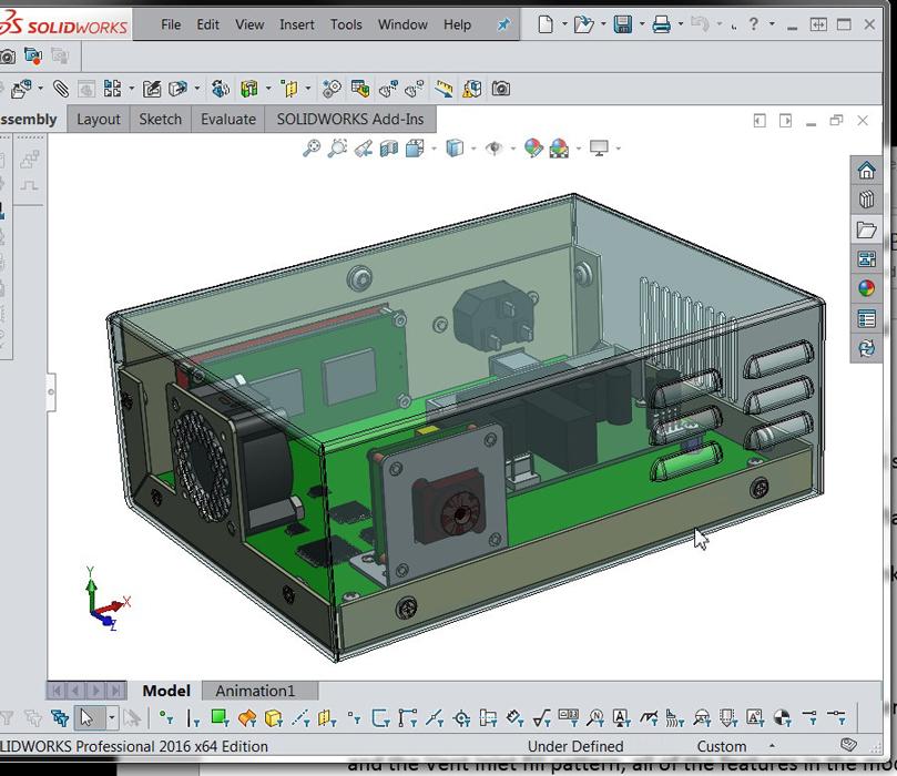
With the exception of renaming the Pin Hole for the camera to see through and the Vent Inlet Fill pattern, all of the features in the model are as created.
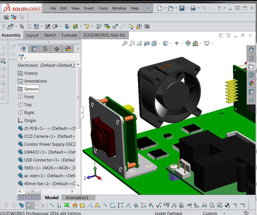
Figure 7 is a screen shot of the entire assembly. This is an imaginary product that might be some sort of automated camera system. The electronics—circuit board, camera, fan, and display—are all modeled in one subassembly. The sheet metal parts are positioned relative to that electronic assembly. The holes in the sheet metal are parametrically linked to the electronic assembly. Screw holes in the cover are linked to nuts in the chassis.
This product development model is relatively easy to modify. For example, the camera can be repositioned, and the holes and bolts automatically follow its position.
Praise of this CAD prototype model aside, the features in the components—sheet metal all the way through to the fan model—were modeled to reveal design intent. In other words, this development model is easy to adapt to future needs. You’re invited to download a copy.
Gerald Davis uses CAD software to design and develop products for his clients at www.glddesigns.com. From 1984 to 2004 he owned and operated a job shop.
Gerald would love to have you send him your comments and questions. You are not alone, and the problems you face often are shared by others. Share the grief, and perhaps we will all share in the joy of finding answers. Please send your questions and comments to dand@thefabricator.com.


The Fabricator is North America's leading magazine for the metal forming and fabricating industry. The magazine delivers the news, technical articles, and case histories that enable fabricators to do their jobs more efficiently. The Fabricator has served the industry since 1970.
start your free subscription
Easily access valuable industry resources now with full access to the digital edition of The Fabricator.

Easily access valuable industry resources now with full access to the digital edition of The Welder.

Easily access valuable industry resources now with full access to the digital edition of The Tube and Pipe Journal.

Easily access valuable industry resources now with full access to the digital edition of The Fabricator en Español.
In this episode of The Fabricator Podcast, Caleb Chamberlain, co-founder and CEO of OSH Cut, discusses his company’s...


