


Contributing Writer
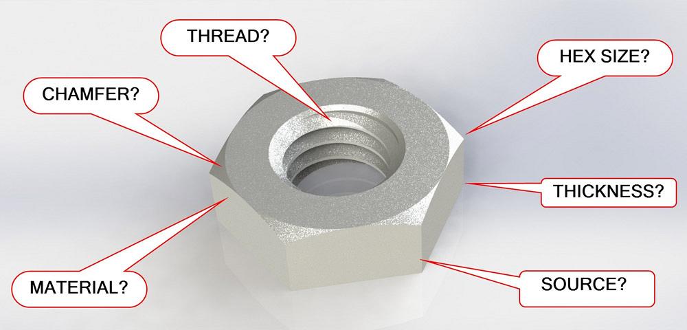
Figure 1a
A CAD model of a nut conveys many details—thread size,
hex size, thickness, and material. The amount of detail is
limited by design intent.
Editor's Note: If you would like to download the 3-D CAD files associated with this column, click here.
Threaded holes present two types of design challenges. In CAD, the modeling technique comes into play. In the real world, practical considerations for fabrication and assembly matter.
Staying with the theme of recent editions of this column, we’re interested in building a library of tools to use in CAD design projects.
Downloads for CAD models of fasteners are easy to come by. Why would one want to model a nut? The answer to that question reveals the design intent behind the model.
Design intent is the answer to many questions. Should we model the thread or just leave it as an annotation on a drawing? Is the chamfer detail needed, or does it just slow down the computer? Should we model each nut size as a separate file or configure one file to represent several sizes?
Tell me what a perfect nut model is, and I can tell you what your design intent is. If the design intent is simply to have a visual placeholder in the CAD, then a download is probably an efficient way to complete the task. Since we’re going to use this model in many of our projects, we want it to be well-crafted. In CAD terms, this implies efficient modeling and use of best practices.
Figure 1a shows a CAD model that we’re going to become familiar with. In this scenario, our design intent is to accurately model all of the manufacturing details. It is possible that we will use a 3-D printer to produce working samples of this item.
Our modeling responsibilities include mechanical information such as flat-to-flat, thickness, and thread form. This model, as an off-the-shelf item, would be even more useful if it included information for procurement.
To extend our scenario, we want to model a variety of common sizes for nuts. Figure 1b shows a range of metric sizes, M6 down to M2.5, as well as inch sizes from 10-32 down to 2-56.
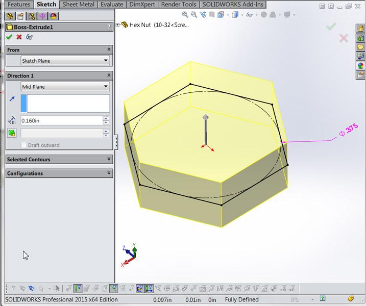
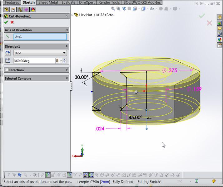
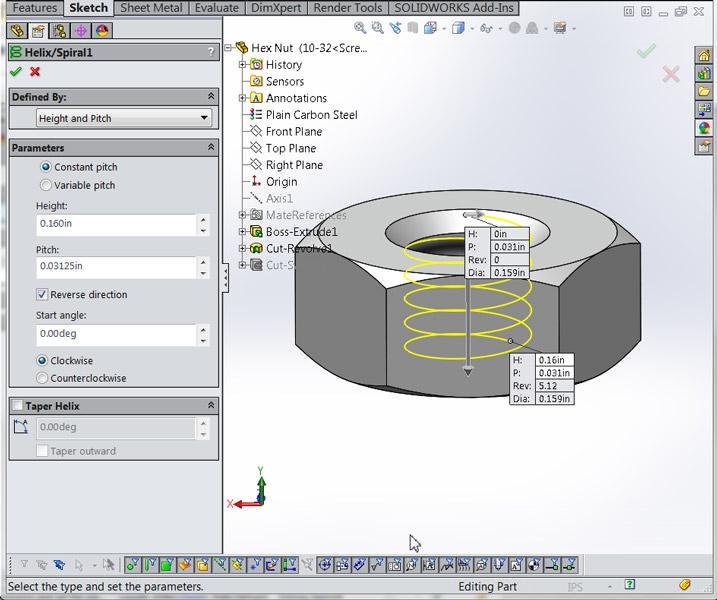
Our nut model begins in Figure 2a with a sketch of a hexagon that is extruded into volume. The 0.375 and 0.160 values were found in a standards table for a 10-32 size. Figure 2b shows the next step of adding the chamfers and the pilot hole for threading. To accurately model the threads, we are going to sketch the thread profile and then sweep it along a helical path to cut the thread into the hex body. Figure 2c shows the setup for modeling the helix.
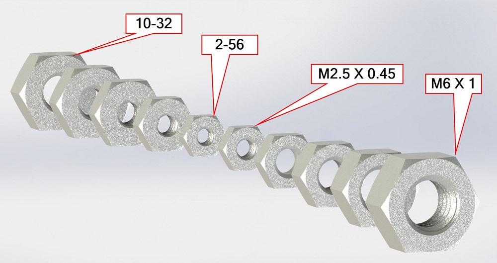
Figure 1b
This image shows a linear pattern of a part in an assembly.
Each instance of the part has been set to a different
configuration to “test” all of the sizes of the nut model.
If you download the sample model (found in the online version of the article on thefabricator.com), you’ll see that the revolved cut in Figure 2b is used to drive the diameter of the helix—a handy trick for configuration table-driven models.
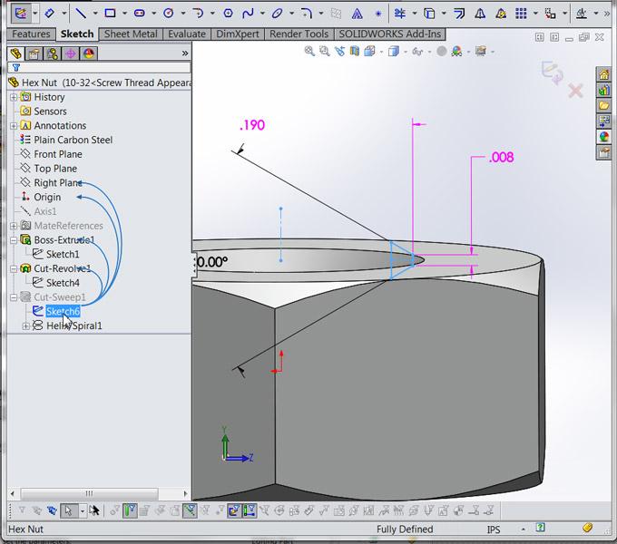
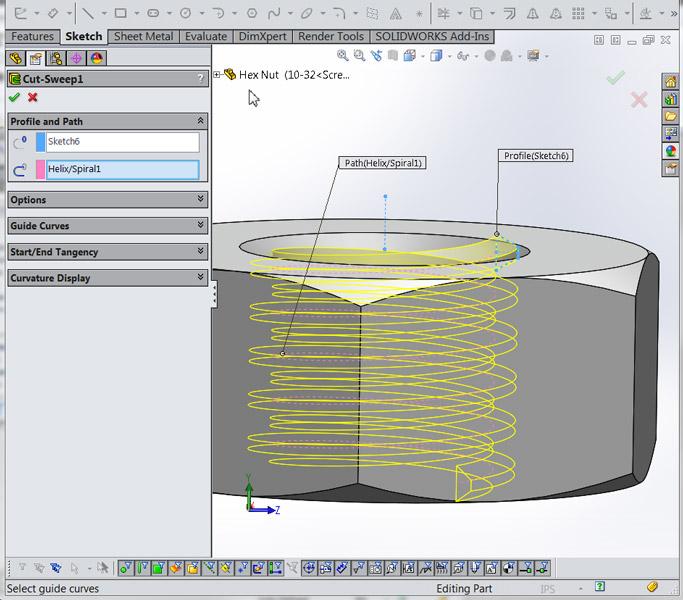
Figure 2d shows the sketch for the thread profile. Again, these initial values were taken from a published standards table. The flank size of 0.008 in., for example, is 25 percent of the pitch rate. Figure 2e shows the swept cut based on the thread profile and helical path.
We now have a model of a 10-32 nut. The next step is to add a design table to create configurations for other sizes of this nut. To help with that, we rename the driven dimensions to give a hint as to what they control.
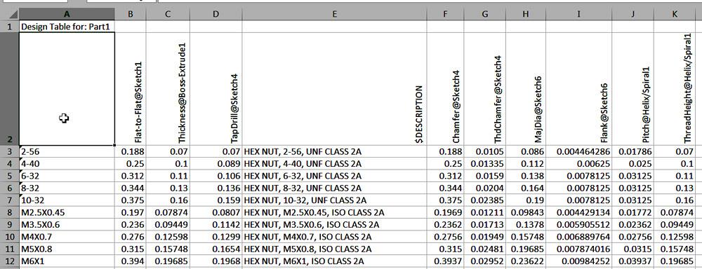
A design table is functionally a spreadsheet that is embedded into the CAD model. Each row in the table represents a different nut size, in this example. Each column is a different feature of the nut.
Figure 3 is a screen shot of our finished design table. Row 7 shows the dimensions for our initial 10-32 nut. The dimension Flat-to-Flat@Sketch1 is set to 0.375 in., and Thickness@Boss-Extrude1 is set to 0.16 in. This matches what we see in Figure 2a. Similarly, the design table sets the values for all 10 versions of this hex nut. Columns are used to control the description, source, and whatever other details we need.
This nut part was inserted into an assembly. That assembly then sprouted a linear pattern of nuts, and each instance in that pattern was set to a different configuration. The result is shown in Figure 1b. This sort of “demo” assembly is a good way to test all of the configurations in a model for side-by-side verification.
The visual accuracy of this model comes with burden: The helical sweep requires computer resources to repaint on the screen. You might decide to create additional configurations that show the model as “simple” or “detailed.” In the simple configuration, suppress the helical sweep.
Adding a Mate Reference to this model will help when it comes to inserting this item into an assembly.
As topics for future discussion, we’ll consider adding threaded holes to sheet metal and machined parts. We’ll also take a peek at manufacturing drawings and specifications for threaded holes.
Gerald would love to have you send him your comments and questions. You are not alone, and the problems you face often are shared by others. Share the grief, and perhaps we will all share in the joy of finding answers. Please send your questions and comments to dand@thefabricator.com.


The Fabricator is North America's leading magazine for the metal forming and fabricating industry. The magazine delivers the news, technical articles, and case histories that enable fabricators to do their jobs more efficiently. The Fabricator has served the industry since 1970.
start your free subscription
Easily access valuable industry resources now with full access to the digital edition of The Fabricator.

Easily access valuable industry resources now with full access to the digital edition of The Welder.

Easily access valuable industry resources now with full access to the digital edition of The Tube and Pipe Journal.

Easily access valuable industry resources now with full access to the digital edition of The Fabricator en Español.
In this episode of The Fabricator Podcast, Caleb Chamberlain, co-founder and CEO of OSH Cut, discusses his company’s...


