


Contributing Writer
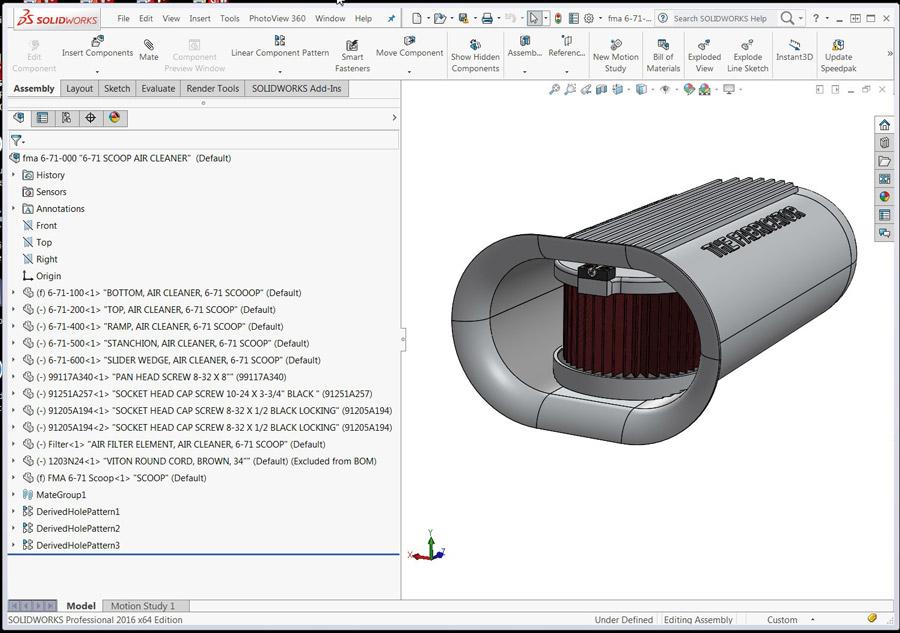
Figure 1
This assembly comprises machined parts, various screws, a filter element, and an aluminum casting.
Editor's Note: If you would like to download the 3-D CAD files associated with this column, click here.
Illustrated progress reports are useful when you are presenting a new design. While a picture can be informative, a moving picture might accelerate the audience’s speed of comprehension.
As a prop for discussing various ways to prepare animations, consider the assembly shown in Figure 1. Several modeled components—various screws, an air filter element, top and bottom plates, a clamping mechanism, and a cast aluminum scoop—make up the assembly. This is an actual product on loan to us for training. (If you’re interested in owning this air cleaner accessory for your hot rod, the editor can put you in contact with who you need to know.)
Here is a typical work flow for design review, once the 3-D modeling is complete:
The model in Figure 1 has constraints that position the components. For example, screws are mated to align with holes. While you develop the 3-D model, remember that those constraints are an important part of having the mechanism behave (during mouse drag) as a realistic virtual prototype.
When the CAD jockey transitions activity from 3-D modeling to 3-D documenting, the modeled constraints conflict with repositioning the components for an exploded view. Fortunately, the 3-D modeling software has a means for ignoring mechanical constraints in favor of exploded steps.
Figure 2 is a screen shot of an exploded view that was created using the 3-D CAD workstation. The software has an Explode tool that disregards mates and allows components to be conveniently positioned with the mouse. A sketching tool—Exploded Line Sketch—is useful for adding the connecting lines between the exploded components. Those connecting lines automatically hide when the view is collapsed.
In Figure 2 you will find the Feature Manager to the left of the graphics window. You likely will notice a list of the explode steps that result in the overall exploded view.
Those explode steps determine how the components are positioned relative to each other. The sequence of those steps controls when the move happens. After the explode steps are created, their order of appearance in the list can be changed with mouse drag.
Some labor is expended in preparing an exploded feature. The skills required for creating an exploded view are not required for invention and 3-D modeling. However, several useful results are derived from the effort that goes into an exploded feature:
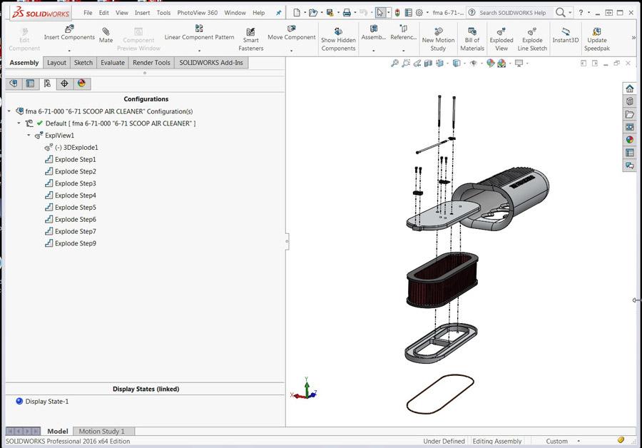
Figure 2
An exploded view is shown as an Explode feature in the Feature Manager. The Explode feature has explode steps. The sequence of steps can be changed by dragging items up/down the list.
This article focuses on that last bulleted item: animations of explode and collapse.
The 3-D CAD workstation offers two methods of animation that take advantage of the labor that went into the exploded view. The effortless method is as easy as a right-click on the explode feature and then selecting Animate. See Figure 3a. The second method involves setting up a timeline populated with event keys, which will be reviewed after a brief tour of the Animate tool.
The Animate tool’s controller—Figure 3b—presents options to loop, reciprocate, and otherwise play. It moves the components according to the sequence of explode steps in the explode feature.
CAD tip: It is easy to change the sequence of explode steps using mouse drag-and-drop.
he Animate tool will also export to an AVI movie file. Here is a movie director’s tip: Create a visual waltz, smooth and graceful. Allow the audience to watch the explode-to-collapse sequence a few times; use subtle changes in point of view to add interest; and end with the components in their starting position.
As for the movie director’s method: Select slow playback speed, and select Reciprocate Mode so the animation seamlessly transitions from one state back to the other. Be prepared to hit the Stop button after you start play with the Save button. (When working with the AVI Settings, consider a frame size of 800 by 600, which should be a good file size. Keep in mind, however, that the frame size of 1,024 by 768 is nicer to watch. Drag the CAD window frame size to approximately the desired frame size. There is no need for perfection. Thirty frames per second results in smooth play, but a large file. Twenty frames per second is probably the useful minimum setting.
Note that the saved AVI grows in size until you hit stop on the Animate tool. Watch the animation on-screen as it is saved to the AVI file. When enough of the animation has been captured, hit the Stop button.
CAD tip: Rotate the model with the mouse at strategic points while the animation is playing/saving. A 3-D controller is a very handy alternative to a mouse for rotating the model.
Here’s one more note: In the event that the AVI needs to be resaved, it requires great dexterity with the mouse to repeat the manual rotation of the view port during AVI save.
In review, the CAD jockey has two convenient tools for changing between explode and collapsed states: Animate tool or instantly toggle.
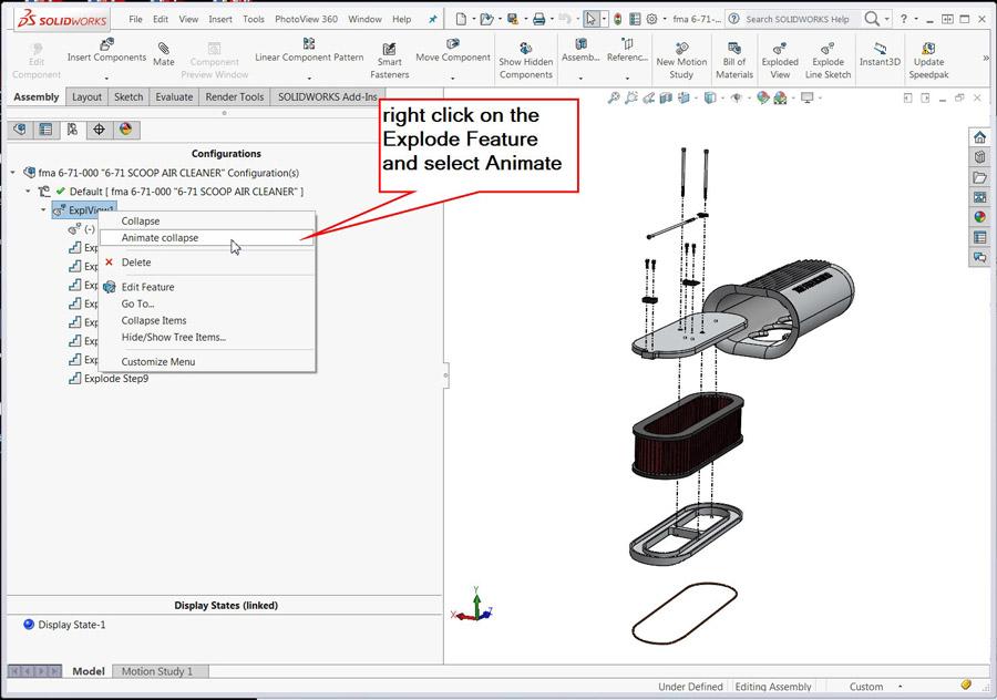
Figure 3a
The Animate tool is launched by right-clicking the mouse on the Explode feature.
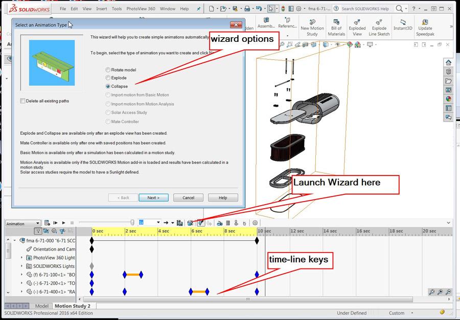
In the event that a CAD jockey in the role of movie director is dissatisfied with the quick and easy, particularly when it comes to controlling the audience’s point of view, add-on software to the basic CAD workstation is available to enable creation of timeline-based animations. Motion study is a licensed feature of the 3-D CAD software referenced in this column. Motion study is useful for creating many types of animations other than explode/collapse.
Here’s another movie director’s tip: Use the Motion Study wizard to automatically create timeline keys derived from the explode feature. See Figure 4. Then drag those explode keys to change when the explode event occurs. This adds interest to the animation. It also is a way to avoid messing with the sequence of explode steps.
As suggested earlier, to improve the explode/collapse movie, the movie director might add timeline keys to control the audience’s point of view. View keys can be created automatically by turning on Enable View Key Creation. Any time the view changes—rotate with the mouse, for example—a key is created. Make it a habit to turn off Enable View Key Creation when it is not needed.
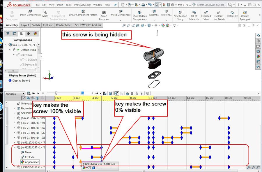
Here’s a movie director’s view key pairing method in two steps (see Figure 5):
1. Drag the play head along the timeline to when the transition to the point of view should be completed. Then use the mouse to change the point of view. This creates a new view key on the timeline. The timeline shows a bar connecting the new view key to the previous view key.
2. Make a copy of the previous view key and paste it before the newly created end-of-transition view key. Position this pasted copy to control when the audience’s point of view should start to change.
The animation can be embellished by adding keys to control the visibility of components. For example, after a screw has “flown out of its hole,” it could fade from sight. A director’s method for creating appearance keys is similar to that recommended for creating view keys. For example, advance the play ahead to the time when the component should hide and then hide it. Go back in time to when the component was visible, and grab a copy of that “visible” key. Paste a copy at the time when the component should start to fade.
Flinty-eyed managers of CAD departments might regard embellishment of animation as a distraction from the refinement of 3-D geometry, but the potential for creating entertaining animations is real. Timeline keys for cameras allow the point of view to fly through the scene, and keys for appearances and section cuts allow for dynamic inspection of internal features. Motors, springs, and the effects of gravity can be included in a study.
CAD tip: Use the right tool for the job. If the 10-minute job is to create an animation useful for review of a design’s evolution, use a Motion Study explode wizard along with a few mouse drags on timeline keys. Caution: If the job is to compose a persistent interactive document, then use other software designed for creating such documents.
The good news is that the workflow for creating animation keys is about the same whether you are composing or working with solid geometry. A pair of keys is needed: One key controls the start, and the other key controls the end of the transition. Copy and paste (or ctrl-drag) is a great way to place the starting key. To create the ending key, position the timeline, then hide, rotate, explode, etc.
Gerald would love to have you send him your comments and questions. You are not alone, and the problems you face often are shared by others. Share the grief, and perhaps we will all share in the joy of finding answers. Please send your questions and comments to dand@thefabricator.com.


The Fabricator is North America's leading magazine for the metal forming and fabricating industry. The magazine delivers the news, technical articles, and case histories that enable fabricators to do their jobs more efficiently. The Fabricator has served the industry since 1970.
start your free subscription
Easily access valuable industry resources now with full access to the digital edition of The Fabricator.

Easily access valuable industry resources now with full access to the digital edition of The Welder.

Easily access valuable industry resources now with full access to the digital edition of The Tube and Pipe Journal.

Easily access valuable industry resources now with full access to the digital edition of The Fabricator en Español.
In this episode of The Fabricator Podcast, Caleb Chamberlain, co-founder and CEO of OSH Cut, discusses his company’s...


