


Contributing Writer
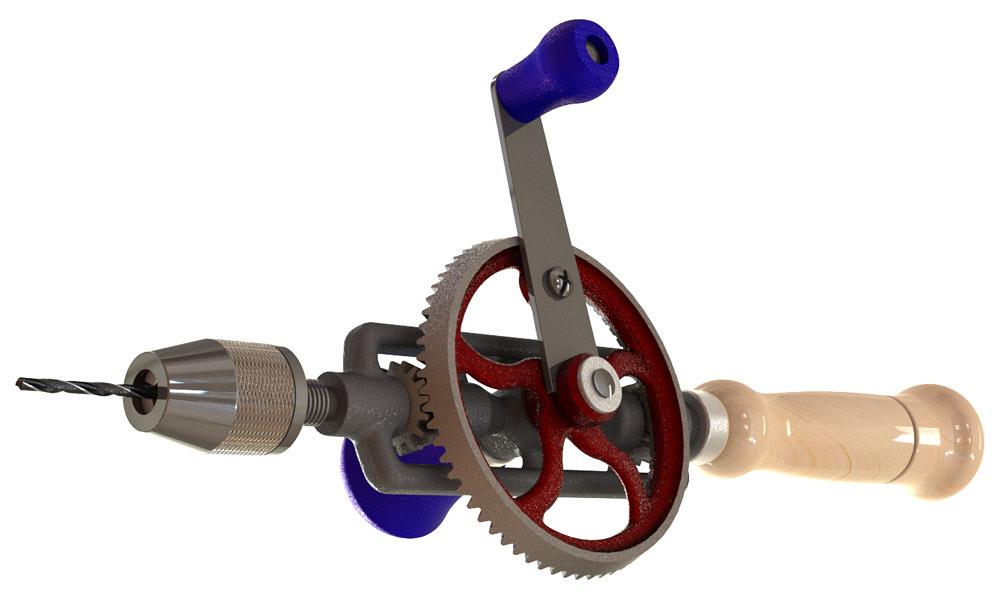
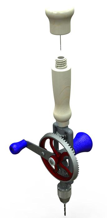
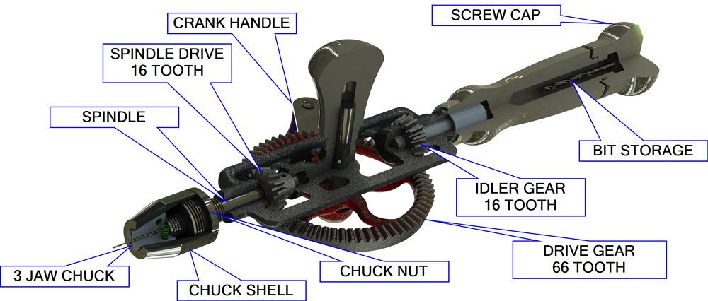
Figure 1a
In this CAD model of a gear drill, the frame is modeled
with drafts suitable for casting. The geartrain operates
correctly. The 3-mm-diameter drill bit gives scale to the
image.
Editor's Note: If you would like to download the 3-D CAD files associated with this column, click here.
The geared drill shown in Figure 1a has a relatively modern design. Such hand-operated drills have been in use for more than 175 years. George Page, when filing a U.S. patent in 1838, claimed that his design “improved on designs that have heretofore been employed.”
“Here’s the drill, Chuck,” Tom said crankily. (Forgive the Tom Swifty. It was hard to resist.)
We’re not so much focused on the merits of this geartrain, nor are we particularly interested in the usefulness of hand drills. In the scenario for this CAD session, we are tasked with producing documentation to explain the product’s function.
CAD tip: Give scale to the image by including objects that the observer is familiar with. Figure 1a displays a drill bit to give a sense of the chuck’s size. This product is definitely something you could hold in one hand.
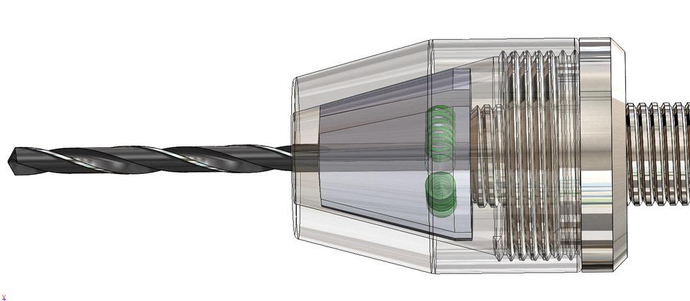
In Figure 1a, the drill has a bit clamped in the chuck. As a prop, the 3-mm bit size is big enough to be fairly easy to identify as a drill bit. In Figure 1b, the bit has been swapped out for a 1-mm size. If you know what you’re looking at, the little whisker in the image does indeed resemble a drill bit.
CAD tip: Sometimes the best way to demonstrate a range of capability is to use side-by-side comparison images, as in Figure 1c. When you present the 3-D model in a live demonstration, your use of configurations makes it easy to show the product in different setups.
This demo model has two drill bits—one visible in the chuck and another hidden in the handle. Figure 1d demonstrates how the handle cap can be removed for storing bits.
CAD tip: Mates accomplish the positioning of components in configurations; configurations turn those mates on or off. Use a Design Table to control both the on/off as well as dimensional values of configured mates.
Figure 1e demonstrates another method of using CAD to illustrate product features—a cut-away view. The balloon comments were added postproduction with image editing software.
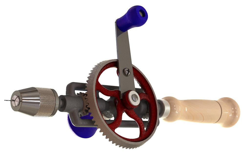
Figure 1b
The 1-mm-dia. drill bit is difficult to see in this image.
The jaws of the chuck have moved to grip the smaller bit.
In Figure 1e, a “zonal” section view appears to slice away 90 degrees of the cast frame of the drill. This reveals internal features of the product. CAD tip: Some items, such as gears and axles, were excluded from the scope of the section view in order to improve the interest of the image.
CAD tip: Props used in image production can be manipulated with the CAD scale tool. In this demonstration, the drill bit model is a downloaded STEP file. After it was imported it was scaled to create a couple of drill bit models that are approximately correct.
When presenting a design concept for review with 3-D CAD, a CAD jockey finds that it is often informative to “operate” the mechanism with a mouse. In the case of this hand drill, the mouse can be used to drag the crank handle, which in turn moves the crank axle, the crank lever, the drive gear, the driven gear, and the idler gear, and it turns the spindle that presses against the tooth that pushes the chuck shell that drags the chuck nut that causes the bit to spin.
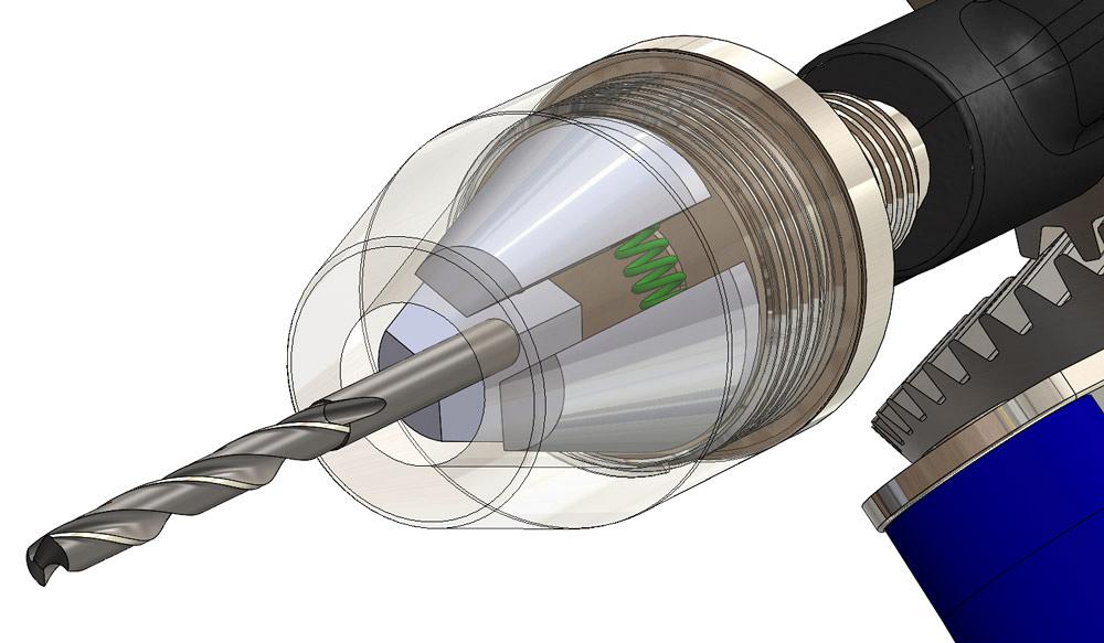
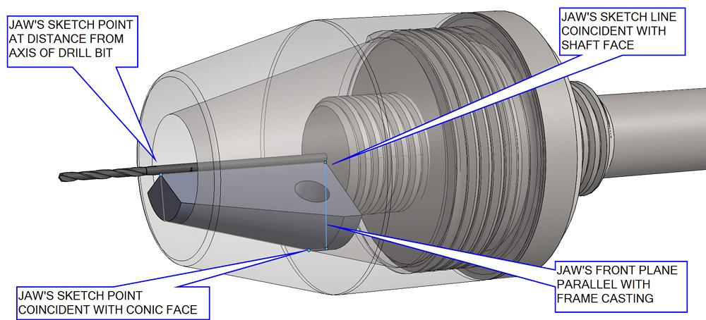
It’s time for a quick quiz: How do you model the chuck so it faithfully unclamps, as in Figure 2a, or clamps the bit, as in Figure 2b, with mouse drag?
This quiz has several goals. The motion of the three jaws inside the chuck shell includes spring pressure that keeps them equally spaced within the cone. As the jaws are pushed into the narrower part of the shell’s cone, the springs are compressed, and the jaws move together. The jaws slide against and make tangential contact with the inside of the chuck’s shell. The jaws also are pressed by the face of the spindle as it screws into the chuck’s nut. Note that the chuck nut is normally removed from the chuck shell only for servicing the jaws.
Part of the CAD modeling answer is revealed in Figure 2c. We see only one of three jaws. This single jaw is actively controlled. The other two jaws will be created by a circular pattern. CAD magic will make all three jaws appear to move correctly, even though only one is doing all of the work.
For convenience’ sake, the model of the single jaw tooth was created by 120-degree, midplane rotation of the jaw’s profile sketch. The sketch is faintly visible in Figure 2c.
The midplane feature in the jaw tooth is handy for mating the jaw so that it doesn’t spin as the spindle screws in and out of the chuck nut. Part of the answer is to mate the tooth to be parallel to some feature on the chuck nut.
In Figure 2c we see that elements of the jaw tooth’s profile sketch are used for mating. Three mates position the tooth within the chuck mechanism:
Limit-Distance mates are great for a mouse drag within the limited range of the mate. Such mates make it easier to pose the model while making various still shots. The limit mates help to goof-proof the motion during live presentations of the model. Without a limit mate, a drill bit could pass through a chuck jaw, for example.
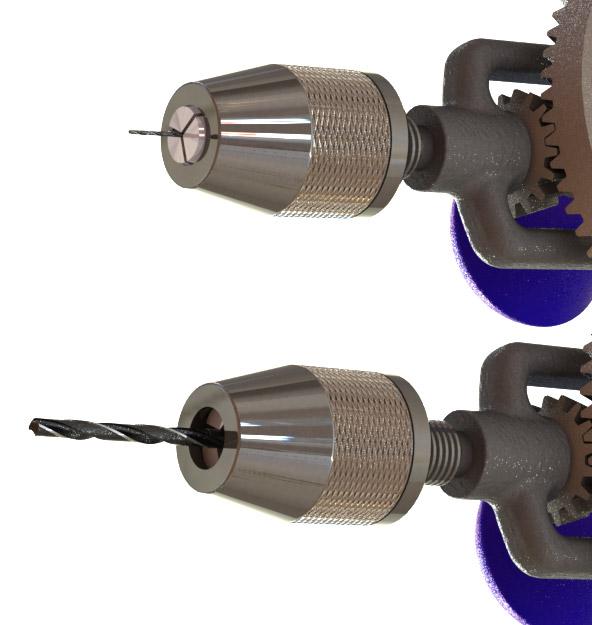
Figure 1c
The range of this product’s
grip is evident in a side-by-side
comparison. Static images can
reveal range as well as scale.
Our work goal according to the original proposed scenario also includes animations (videos) to go along with the still shots needed for print. Distance mates with a single value are handy as controls when creating animations. Values can be controlled, whereas limits are beyond the control of certain animation programs.
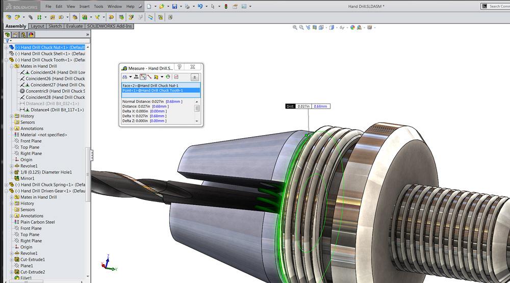
Now it’s time for the CAD quiz summary. In Figure 2d we see the result of setting the distance mate between the jaw and the bit. This starts a chain reaction in the mates we have set up. The jaw must stay in contact with both the inside cone of the shell and with the flat face of the spindle. As the jaw moves to the specified distance from the bit, the chuck shell is pushed away from the spindle. The shell drags the chuck nut along with it. The screw mate with the spindle and chuck nut causes the chuck nut to spin about the axis of the spindle and to unscrew from the chuck nut. Thanks to the frictionless magic of 3-D CAD, the behavior of the mated parts in the chuck is visually similar to a real-world machine.
Another product feature is emphasized in Figure 2d: The jaw teeth get closer to the chuck nut as the distance from the bit is increased. A gap of 0.027 in. is shown in the illustration. As a side note, this chuck design can almost open up enough to grip a 0.234-in.-diameter bit. We’re looking at a 0.117-in.-dia. drill bit in Figure 2d.
What happens if that gap between tooth and nut goes to zero? At that point, the jaws cannot open any farther, and the chuck will simply unscrew from the spindle.
The page upon which this article is published pre-sents static illustrations very nicely. If you’re interested in the dynamic details of motion and modeling of this hand drill, we encourage you to download the SW15 model to study that media also.
Behind the scenes, we’ve used configurations of the CAD model to display various props and modes of operation. We also use configurations to toggle the model from drag mode to movie mode.
The objective behind our mate management plot is to suppress limit mates that were useful for mouse drag and unsuppress mates that rigidly lock the model in position—perfect for a Motion Study, a brand name for animations.
A Motion Study will then be used to change the value of various distance mates over time. This creates repeatable animation. This is a topic for a separate article, but these types of animations use key points in time to set a value. For example, at time 1:00, the mated distance is 0.234 in., while at time 2:00 the distance is 0.117 in. When the animation is played, the Motion Study varies the mated distance within the specified key points.
Here are a couple of links to example videos that show how our chain of mates behaves when the distance to the drill bit and jaw tooth is varied: https://youtu.be/66ey6lNiyvw and https://youtu.be/JBsebRuQCEU.
We also added some motors to make things turn, added a camera, and flew around the model.
The CAD tools demonstrated in this article are well-suited for engineering, design, and development of mechanisms. The mates constrain the model to behave in a controllable and predictive way. Sometimes the required chain of mates gets exotic. Nonetheless, these are outstanding tools for designing tools, gear-driven hand drills, for example.
What if you just need documentation for assembly and ownership of a tool like a hand drill? Is all of this mastery of mates required? Stay composed. We’ll be looking at other tools that use 3-D CAD models to prepare documentation.
Gerald would love to have you send him your comments and questions. You are not alone, and the problems you face often are shared by others. Share the grief, and perhaps we will all share in the joy of finding answers. Please send your questions and comments to dand@thefabricator.com.


The Fabricator is North America's leading magazine for the metal forming and fabricating industry. The magazine delivers the news, technical articles, and case histories that enable fabricators to do their jobs more efficiently. The Fabricator has served the industry since 1970.
start your free subscription
Easily access valuable industry resources now with full access to the digital edition of The Fabricator.

Easily access valuable industry resources now with full access to the digital edition of The Welder.

Easily access valuable industry resources now with full access to the digital edition of The Tube and Pipe Journal.

Easily access valuable industry resources now with full access to the digital edition of The Fabricator en Español.
In this episode of The Fabricator Podcast, Caleb Chamberlain, co-founder and CEO of OSH Cut, discusses his company’s...


