


Contributing Writer
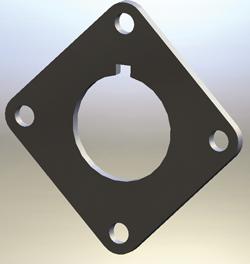
Figure 1: This adapter plate is the design goal.
There's nothing sketchy about the general skills involved in sketching. You need to be able to create sketch entities, establish sketch relationships, and add dimensional features.
When I'm drawing a sketch, I have a habit of roughly sketching the shape I'm imagining without worrying about the dimensions or sketch relationships. The first stage is more like doodling than anything else. I make full use of the tools that let me stretch or trim the sketch entities. Once I have what approximately resembles what I'm looking for, then I'll start adding sketch relationships. The final step is to add dimensions to control the size of things.
Figure 1 shows the part that we're going to design. Let's think of it as an adapter plate. You could model this part several different ways, but the method I'm using is intended to be more illustrative than efficient. If you find a better way, I wouldn't be surprised.
In Figure 2a you can see that I've sketched two construction lines and two circles. No effort went into making them any particular size. We'll use the circles to define the holes, and the construction lines to create the part's symmetrical features. Note that the circles and lines are called sketch entities. Other sketch entities include arcs, splines, and points. However, those are not being demonstrated in this example.
InFigure 2b I've added sketch relationships. One of the construction lines is now vertical and the other is horizontal. Both of the circles are now equal. Oh, yes. I also made both of the construction lines equal to each other.
You may also notice that things in the sketch are changing color. Blue (on my workstation) means that the sketch entity has at least 1 degree of freedom. Black means that the sketch entity is fully constrained, or that it can't be accidentally moved.
I don't always fully constrain my sketches. Some may regard that as lazy. I consider it to be efficient. If it matters, I constrain it. Otherwise, I just let it be.
The drawing is getting a bit more complex in Figure 3a. I selected the vertical construction line and the circle to its right and used the mirror tool to create a symmetrical copy of the circle. I repeated the process with the horizontal construction line and the circle at the top.
In Figure 3b I've added a dimension to set the diameter of one of the circles. I also added a single dimension to set the distance between the circles. Note that the other three circles immediately changed size and position because of the sketch relations (equal and symmetric). All sketch entities are black in color, which indicates that the sketch is fully defined.
From this you can see that a combination of sketch relationships and dimensions can be used to set up a sketch that is easy to edit. By changing one dimension, I can change the size of all of the holes. By changing the other dimension, I can edit the distance between all of the holes.
Next I want to create the perimeter of the part. I'll do that by using the offset tool as shown in Figure 4a. The amount of the offset isn't critical in this part, so I just used something similar to what the material thickness will be. All four of the circles were offset by the same amount.
In Figure 4b I've sketched lines between the offset circles. The computer automatically created most of the tangent sketch relationships for me by inferring from my mouse position when I clicked that that was what I wanted. Sometimes the automatic sketch relationships are more of a nuisance than a blessing. If that is the case, you can use the SHIFT key while clicking the mouse to prevent them from being created.
Once all four of the lines were set as tangent to the corresponding circles, the sketch was again fully defined. InFigure 5a I'm using the contour select tool to select the regions of the sketch that I want to extrude into a solid. I could have used the trim tool to eliminate extra geometry in the sketch, which might have been more elegant. Unless there is a compelling reason not to, why not use a process that requires fewer mouse strokes?
Figure 5b shows the resulting 3-D part. The next step is to create a cutout in the middle of our adapter plate.
In Figure 6a I've roughly sketched three sketch entitie—a circle, a construction line, and a rectangle. One end of the construction line lies at the midpoint of one line in the rectangle.
In Figure 6byou can see that I set the construction line to be vertical. Because of its midpoint relationship with the rectangle, the rectangle is now symmetrical in the sketch (even though it does not have a symmetrical relationship). I added dimensions for the circle and the size of the detent notch that I care about.
Note that one line is still blue—it is not fully constrained. Again, some people might prefer to fully constrain the sketch, but the software doesn't care either way.
In Figure 7a I'm using the contour select tool to select the regions of the cutout. The finished part is shown in Figure 7b. The only difference between Figure 1 and Figure 7b is that I added texture and color to Figure 1 for glamour.
The specific steps used to create sketch entities will depend on the software that you're using. Every 3-D CAD system that I've played with makes the sketching process very easy once you get accustomed to it.
One of the nice features about the software I use regularly is the ability to switch between drawing lines and arcs by simply dragging the mouse over the end point of the last entity sketched. The mouse pointer makes it clear which kind of sketch tool is currently active.
I have several objectives when I'm working on a sketch. I want to complete the sketch quickly. I don't want any redundant or duplicate relationships or dimensions. Perhaps most important, I want the sketch to be easy for me to understand and edit in the future. Simplicity is generally a blessing, not only for me, but for the computer as well, because it has to interpret all of my doodles, relationships, and dimensions.
When I inherit a 3-D CAD model from another person that is heavy—hard to manipulate with the mouse—I generally start looking at the sketches with an eye for eliminating unneeded sketch relationships and dimensions.
A 3-D sketch is a lot like a 2-D sketch, except that you get more automatic help from the computer while doodling in a 2-D sketch. The computer always assigns X,Y, and Z coordinates to every point. In the case of the 2-D sketch, the Z coordinates are always equal to the sketch plane you've selected, so you don't have to fuss with them.
In a 3-D sketch, you are responsible not only for the X and Y coordinates, but also for defining the Z coordinates. Because you're working on a flat 2-D monitor, visualizing the 3-D space can be challenging. To give you a fair shot at getting the work done, the software will give you tools to select your point of view.
You'll also be able to set sketch relationships in a 3-D sketch, but instead of simple horizontal and vertical, you'll have Along X, Along Y, and Along Z. To help with this, the software will probably allow you to set a default orientation for creating automatic sketch relationships as you doodle.
Next month I'll take a closer look at dimensioning techniques to compare ordinate, baseline dimensioning methods, as well as how those sketch dimensions relate to the dimensions that appear on a mechanical drawing.
Gerald would love to have you send him your comments and questions. You are not alone, and the problems you face often are shared by others. Share the grief, and perhaps we will all share in the joy of finding answers. Please send your questions and comments to dand@the fabricator.com.


The Fabricator is North America's leading magazine for the metal forming and fabricating industry. The magazine delivers the news, technical articles, and case histories that enable fabricators to do their jobs more efficiently. The Fabricator has served the industry since 1970.
start your free subscription
Easily access valuable industry resources now with full access to the digital edition of The Fabricator.

Easily access valuable industry resources now with full access to the digital edition of The Welder.

Easily access valuable industry resources now with full access to the digital edition of The Tube and Pipe Journal.

Easily access valuable industry resources now with full access to the digital edition of The Fabricator en Español.
In this episode of The Fabricator Podcast, Caleb Chamberlain, co-founder and CEO of OSH Cut, discusses his company’s...


