


Contributing Writer
Figure 1a: This sheet metal bracket model is an example of an assembly of components.
We live in a 3-D world, so it makes sense that metal fabricators would work with 3-D CAD assemblies as a typical part of their work life. Fortunately, working with 3-D CAD assemblies also has many advantages.
(Before delving too much into the benefits of 3-D CAD modeling technique, I should acknowledge that much of the terminology being used is specific to a particular software package. Even if you prefer using a different CAD system, most of the concepts being discussed still will apply.)
Figure 1a is an example of a 3-D CAD assembly. This sheet metal bracket has two captive fasteners swaged into it. Each of the three parts—the bracket, the stud, and the nut—are modeled and stored in separate CAD files. A fourth file—the assembly file—positions the parts in their correct relationship to each other.
Figure 1b shows the exploded view of the assembly. This might make it easier to identify the individual components.
One significant advantage of 3-D CAD modeling of assemblies is that it mimics the way that the part actually will be manufactured. For example, it might be important to see how the parts go together when planning access for the tooling needed to install the captive fasteners. For more complex assemblies, 3-D CAD modeling can help with visualizing the sequence of assembly. This modeling method can also be great for creating illustrations for owner's manuals.
After putting great effort into designing a great product, a CAD operator finds it nice to get as much help as possible from the CAD system when it comes to the detailing work. Assemblies make it easy to create a bill of materials (BOM) in the drawing (see Figure 2).
The table in the lower right corner of the drawing was completed with just a few mouse clicks. The software filled in the quantities. Because the source information and descriptions were already in the models that were reused for this example, an accurate BOM was easy to create.
Because each component part is modeled separately, a parts designer can find it easy to manage the detail level of the model. In this example, material properties have been assigned to each component. The captive fasteners are stainless steel, and the sheet metal bracket is aluminum. Figure 3 shows a screen capture of a mass properties report based on the completed assembly. The report shows the mass (0.095 lbs.) and where the center of gravity is. For some applications, knowing the weight and center of gravity can be very important.
In this type of modeling, each component that goes into the assembly brings with it the detailed information about mass, source, cost, and part specs. As a result, the generation of accurate documentation to support purchasing, manufacturing, and customer service is much more automated.
Another benefit of modeling the project as an assembly is the opportunity to reuse the models in other projects. Figure 4 shows another assembly that uses the identical model of the captive stud. In this example, three copies of the stud were used in the assembly to create a tripod bolt pattern. In many cases, you can find 3-D CAD models on the Internet. This can save you time as well as improve the accuracy of your project.
Perhaps the most dramatic reason to model a project as an assembly is that an animated model can provide a visualization of how a mechanism operates. Figure 5 shows a model of a lever-operated metal punch. The model behaves very much like the real thing. When you "lift" the lever with the mouse in the CAD program, the punch retracts from the die. Being able to study a design in motion can cut down on the number of prototypes needed to get a project into production manufacturing.
When you consider the advantages of realism, kinematics, and design reuse, shouldn't models always be created as assemblies? The answer depends on the design intent—the reason you're taking the time to create a 3-D model of the project.
That specific reason will drive which modeling techniques are selected. Sometimes the design intent will be to produce a model quickly with minimum effort, suitable for conveying a concept. Other times the model will need exacting detail, suitable for conveying manufacturing details.
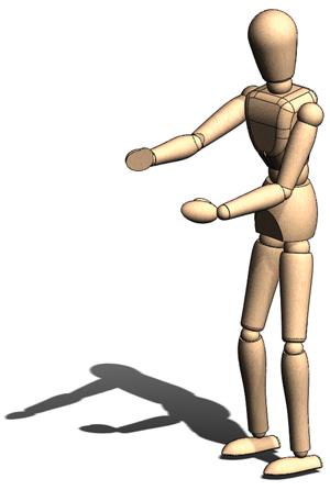
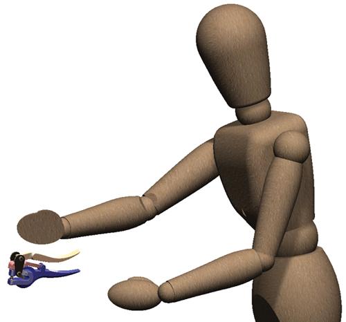
Consider the mannequin shown in Figure 6a. If the model needs to be positioned in different poses, an assembly is a good option. If the model is just a prop to illustrate relative size (as shown in Figure 6b), then perhaps it would be best to model the mannequin as a single part.
Modeling projects as assemblies requires attention to several details. First, a CAD operator must cope with a plethora of file names. Organizing and maintaining a design library can be a laborious task. If it is neglected, the library can wind up with lots of duplicate files. The worst result is to lose track of where a model file is and end up re-creating it.
Second, the components that go into an assembly must be mated to establish their relationship to each other. While mating components together isn't difficult, it can be tedious and time-consuming. For example, the lever punch model shown in Figure 4 has 39 mates to connect the screws, axles, levers, and other parts together.
While undoubtedly other nuisances arise from using assemblies, I'll end my rant with a caution about parts that are common to several assemblies. The good news is that if a revision to the common part is needed, then making the change once to its part file will be propagated automatically to the other assemblies that use it when they are opened. The bad news is that if the change wasn't supposed to propagate to all of the assemblies, then you're stuck figuring out how to manage that.
A solution is to model the project as a single part (see Figure 7). When this is done, everything is contained in a single CAD file. It didn't take too long to model. In this case, it took just a little bit longer than it took to model the assembly, but I already had the captive fastener models completed before I started the assembly.
The problem with Figure 7 is that it will require a lot of work to add detail to it to make it as realistic as the model shown in Figure 1a. An exploded view like in Figure 1b will take even more work—bordering on the impossible.
The cool thing about Figure 7 is that if this model is posted on the Internet, other people will be able to use the product in their designs, but they won't know what it is made from. The physical size can be shared without revealing proprietary secrets about the internal workings.
Perhaps the most compelling reason to model this project as a single part, instead of as an assembly, is that it reduces the burden on the computer. If this part is used many times in a complex assembly, attention to rebuild time can be important. Otherwise, the model will be slow to view and rotate, which can make editing a laborious chore.
A new body of emerging technology in the 3-D CAD software tries to leverage the advantages of both modeling techniques (assembly and single part). Part files can be split, and the resulting multibody models can be manipulated much like an assembly. Layout sketches can be used to create a part file that has kinematic behaviors that strongly resemble a conventional assembly. I'll be writing about these and other modeling techniques in future articles.
For now, this "old-school" idea of modeling a collection of components and then mating them in an assembly is an important foundation skill for you to master as a steely-eyed CAD jockey.
Gerald would love to have you send him your comments and questions. You are not alone, and the problems you face often are shared by others. Share the grief, and perhaps we will all share in the joy of finding answers. Please send your questions and comments to


The Fabricator is North America's leading magazine for the metal forming and fabricating industry. The magazine delivers the news, technical articles, and case histories that enable fabricators to do their jobs more efficiently. The Fabricator has served the industry since 1970.
start your free subscription
Easily access valuable industry resources now with full access to the digital edition of The Fabricator.

Easily access valuable industry resources now with full access to the digital edition of The Welder.

Easily access valuable industry resources now with full access to the digital edition of The Tube and Pipe Journal.

Easily access valuable industry resources now with full access to the digital edition of The Fabricator en Español.
In this episode of The Fabricator Podcast, Caleb Chamberlain, co-founder and CEO of OSH Cut, discusses his company’s...


