


Contributing Writer
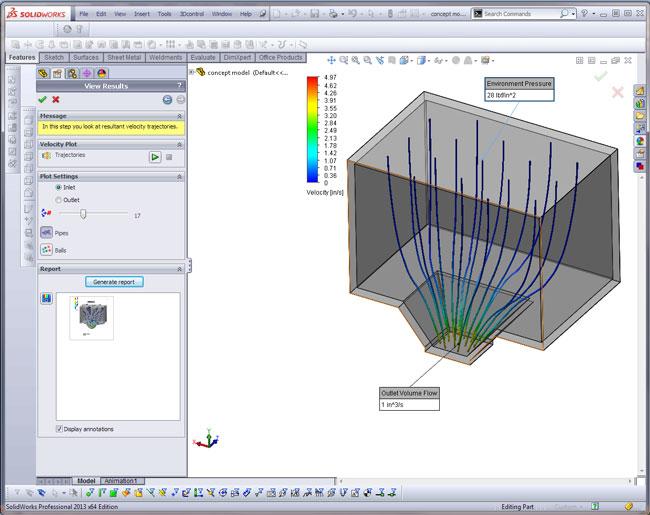
Figure 1: Steps in the product development cycle include invention, calculation, virtual prototype, prototype, first article, and mass production. This illustration shows the product in the calculation phase.
In the step-by-step process of product development, there comes a time when the virtual prototype, or 3-D CAD model, is to be transformed into a fabricated item such as a prototype, first article, inspection sample, or production piece.
Let’s assume an example scenario of a business that needs a custom-fabricated item (the customer) and a business that produces such items (the shop). Figure 1 shows a screen shot of a product during a development phase of the design. Figure 2 shows a summary of the customer’s resulting sheet metal design.
While the design in Figure 2 seems to satisfy the physical requirements of Figure 1, there are issues with material thickness, inside bend radius, and suitability of the alloys for bending and welding, as well as challenging gaps for bending and difficult parts to clamp for welding.
As we follow the flow of intellectual property, the design is developed by the customer, presented to the shop, refined for manufacturing, revised for accurate documentation, tooled for production, and fabricated. Clearly the customer owns the design and benefits from all of the modeling and editing features that 3-D CAD offers, so the customer wants to maintain all of the CAD data history that is native to its version of 3-D CAD software.
“Tooled for production” information could include shop drawings, custom-made tooling, extremely clever production engineering, and control programs for CNC machinery. The ownership of such technical intellectual property probably resides more with the shop than with the customer. A typical mutual nondisclosure agreement is that the shop must not reveal the customer’s design secrets, and the customer must not reveal the shop’s manufacturing secrets. The specifics of your situation should be evaluated with professional legal counsel.
Refining the design for manufacturing can vary from “none allowed” to “the contract requires providing a 3-D CAD model” to the customer matching the fabricated part. Somewhere in between those extremes, the customer allows the shop to change the design.
The shop makes suggestions (see Figure 3) to improve the efficiency of fabrication for the product shown in Figure 2. The suggestions include using a ductile aluminum alloy for forming; 5052-H32 also is suitable for gas tungsten arc welding. The recommended thickness (0.080 in.) is readily available. To help with the forming, the inside bend radius and bend gaps now match standard tooling. Last, the notches and tabs make the assembly much easier to clamp during the welding process.
In the example scenario, the shop and the customer independently operate their 3-D CAD systems. There is no coordination of brand names or software versions.
Fast Exchange Rate. Fast, accurate, and simple moving of data from one CAD workstation to another is important to smooth business operation.
The 3-D CAD software that I am most familiar with has three tools that are important to this discussion:
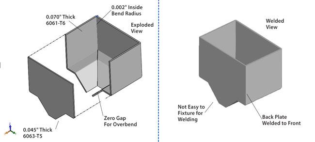
Figure 2: The original design calls for nonstandard material thickness, poor choice of alloys, and difficult dimensional features to create.
“Dumb” Models Are Good Models. One of the consequences of importing a 3-D CAD exchange file to create a new 3-D CAD model is that the design history of the data is lost. That might be a curse. For a 3-D CAD model that is going to be subjected to significant or constant revision and design change, it is very useful to have that design history.
In the example scenario, however, the loss of history is a blessing. The shop likes the idea that the design will be difficult to alter or edit. The shop wants to produce exactly what the customer expects. Importing a 3-D CAD exchange model from the customer is a fine way to go.
What about designs that are not really suitable for manufacturing? Should the shop really ship to the customer exactly what it modeled, or should the shop ship a product the customer can use?
The differences in the designs in Figure 2 and Figure 3 are examples of discrepancies between what is easy to build and what is easy to design. All too often there is a significant gap between the two. This frequently is a consequence of designers focusing on development intent rather than physical process. 3-D CAD techniques that please the computer don’t always result in designs that match available tooling. That is why the shop’s contribution of expertise to the design can be very important to successful product fabrication.
With the feature recognition tool, the shop can start with an imported 3-D model and create a design history out of thin air by having the software reverse-engineer the imported model. The goal of reworking the CAD design is not only to produce a great physical product, but also to produce clear documentation—a CAD model to match the first article—that can be returned to the customer.
If the shop is just whacking the model to fix bend radii or material thickness, plenty of tools are available for working with the “dumb” model (the 3-D model that has no design history or parametric features).
Another reason to export a model, import it, and then use the CAD feature recognition is to create a pristine modeling history. It is a way to simplify a CAD model, at least when it comes to the CAD techniques used to create the finished shape. At times the model gets so edited and patched that it is best to start over with a clear vision of the design intent. Feature recognition is a CAD trick that sometimes helps to speed that process of starting over.
In the example scenario, there is no requirement for feature recognition. The shop can work with the imported 3-D model. However, the customer’s design has some discrepancies with the shop’s tooling. Hole size is mismatched, and there are issues with the bend radius and bend relief. Fortunately, the design is fine for forming; the flanges are long enough and the pressure required for bending is within the shop’s capability.
After the shop uses various CAD modeling techniques to edit the imported version of the customer’s design, it produces an accurate flat layout, as well as a design that is compatible with its machinery.
The shop has several options for sharing the improved CAD model with the customer. Exporting the CAD to a file and then sending that to the customer has several benefits. One of the small benefits of stripping history from the model is that it keeps the shop’s trade techniques in-house. The shop doesn’t have to show the customer how to insert bends or use hybrid modeling techniques.
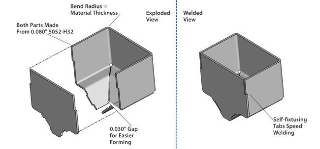
Figure 3: The suggested design calls for standard material thickness, excellent choice of alloys, and easier features to build—self-fixturing for welding.
Perhaps the greatest benefit of using a CAD data exchange file such as STEP or IGES is that software versions don’t have to match at the shop’s and customer’s workstations.
The shop needs to discuss with the customer the nuances of using STEP files for exchange of design for manufacturing. If the customer is interested in receiving the shop’s improved CAD work, the shop will negotiate the fee, as well as the format and scope of responsibility.
In some situations, minor discrepancies—the size of the bend relief or the exact inside bend radius—are allowed. They are just for reference. In other situations, the shop will need to inform the customer before production starts of changes that it wants to make. The shop might need the customer’s approval before tooling up its version of the design.
In the latter situation, the customer can import the improved STEP file using its 3-D CAD software to compare the proposed model to the original. In a quick visualization, the customer can evaluate the merits of the suggestions.
The shop can use its workstation to create reports and screen shots showing the customer’s design in comparison to the shop’s design. The shop then can provide that data to the customer to facilitate approval of its work. The screen shot in Figure 4 shows the use of a built-in compare utility. The lower section of the display shows the material that was removed. A mouse click switches among “removed,” “added,” and “common” to present clearly the differences between the original design and the suggested design.
While I recommend the STEP file format over any other, it’s largely a matter of preference. The IGES data exchange standard predates STEP. IGES is good but old. STEP incorporates all of the goodness of IGES in a modern wrapper. STEP files zip up into small files for e-mailing. When negotiating with a customer about file formats, pick a STEP—STEP 203 or STEP 214—and make that your exchange standard.
Gerald would love to have you send him your comments and questions. You are not alone, and the problems you face often are shared by others. Share the grief, and perhaps we will all share in the joy of finding answers. Please send your questions and comments to dand@thefabricator.com.
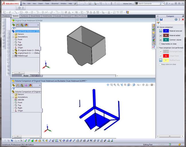
Figure 4: 3-D CAD software can be used to compare two models to see what has been removed, added, or just what is common between the two designs. This screen shot shows that the suggested model changes some of the inside bends and makes a slight positional difference to the floor of the chute.


The Fabricator is North America's leading magazine for the metal forming and fabricating industry. The magazine delivers the news, technical articles, and case histories that enable fabricators to do their jobs more efficiently. The Fabricator has served the industry since 1970.
start your free subscription
Easily access valuable industry resources now with full access to the digital edition of The Fabricator.

Easily access valuable industry resources now with full access to the digital edition of The Welder.

Easily access valuable industry resources now with full access to the digital edition of The Tube and Pipe Journal.

Easily access valuable industry resources now with full access to the digital edition of The Fabricator en Español.
In this episode of The Fabricator Podcast, Caleb Chamberlain, co-founder and CEO of OSH Cut, discusses his company’s...


