


Tips for welding preparation
How machine, materials, and tool bits affect the results
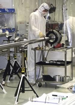 |
Advances in equipment automation and the development of new and exotic tubing materials have affected welding techniques and weld preparation. The levels of cleanness required in many industries—medical, electronic, aerospace, chemical, pharmaceutical, agricultural, and semiconductor—have driven high-purity welding requirements, which in turn drive higher standards in weld preparation.
As welded tubular products have become more complex, manufacturers have turned to using more stainless as well as exotic metals, such as titanium and various alloys. Cold cutting with tool bits is one technique used to cut these materials in preparation for welding, and the tubing materials and surface treatments change the characteristics of this cutting process.
Equipment and Bit Choices
Many portable weld end preparation machines have been designed to cut tube ends precisely enough for automatic welding. This equipment can reliably cut conventional carbon and stainless steel tubing, as well as some exotic materials, such as INCONEL® and MONEL® alloys, Hastelloy®, titanium, and various types of aluminum.
End-squaring machines are designed to square the ends of thin-wall tubing or pipe for autogenous (without filler material) butt welding. These machines generally use specialized tool bits to produce square ends with minimum burr, as well as collets that mount on the OD to hold the tubes round and to prevent damage to tube bores. These machines are suitable for use in clean rooms in semiconductor and pharmaceutical facilities. Optimum weld joints require the ends to be flat for minimum gap and burr-free to keep the arc centered on the joint.
Tube severing or cutoff machines mount to tube via clamping "saddles," or three-piece tapered collets. Some machines feature lever-actuated or pneumatic clamping, as well as autocycle tool modules that perform the cut and return to home, ready for the next cut.
Pneumatic and electric chipless tube cutters are available that can perform a rapid, precise sever of tubing without producing cutting debris. These chipless cutters are suitable for system maintenance, as well as remote operations, in which they can be used in conjunction with tubing connectors.
Obtaining the best results with any of this equipment requires selecting the most appropriate tool bit for the material being cut. Tool bits with a too low entrance angle push the chip, causing the chip to rub hard on the tool bit hook radius, which in turn causes the tool bit to overheat. A high enough entrance angle and large enough hook radius are required to let the chip flow easily off the tool bit, carrying with it most of the heat generated by the cut. Tube-squaring bits use an entrance angle that is much higher than the entrance angle of a typical tool bit; the higher angle reduces the tendency to push burrs to the OD or the ID of the tube end.
Guidelines for selecting tool bits include the following:
- Use a standard-entrance-angle tool bit for carbon steel. These bits also may function well and have a longer life on some stainless steel applications in which a nearly burr-free end is not critical.
- Use a high-entrance-angle tool bit for most stainless steels. This generally is the most suitable edge geometry for 90 percent of all stainless steel tubing.
- Use an extra-hook-angle tool bit for soft stainless steels such as 316L, which have been bright-hydrogen-annealed, vacuum-annealed, or annealed and electropolished. The latter material runs as low as 76 Rockwell B, as opposed to higher than 80 Rockwell B for typical drawn tubing. Also, electropolished stainless steel has a microthin surface that is high in chromium and nickel, making it very soft but tough and difficult to cut without creating burr.
Material Concerns
All materials cut differently. Tool bit wear and final cutting results vary greatly depending on the type of material, wall thickness, coolant used, feed rate, and surface speed of the tool bit.
All machinable metals have unique characteristics that affect tool bit performance and life. For example, each metal has a different shear plane angle that results from its composition and alloy structure. For maximum performance, tool bit design should address the optimum shear angle for each material.
It is not enough to specify the process controls for the material designation without including the heat treatment and surface treatment. For example, annealed and electropolished stainless steel has characteristics that are significantly different from those of drawn tubing. In addition, the thermal conductivity, abrasive characteristics, and shear toughness of the material affect the amount of heat generated in cutting and whether it dissipates into the tool bit, workpiece, or chips.
Almost all titanium tube and pipe products are made from alloys grouped as commercially pure or alpha-beta alloys. In general, these alloys do not reach a hardness greater than 35 Rockwell C or a yield offset tensile strength greater than 70 kilopounds per square inch. As such, they remain relatively easy to cut, as long as the right procedures are used to cut them. The beta group of titanium alloys, which can be heat-treated to a high tensile strength, are the more difficult alloys to work with.
Difficulties in cutting titanium and the high-nickel-content INCONEL and Hastelloy alloys usually result from using an excessive surface speed. These alloys have very low thermal conductivity; reducing the cutting speed prevents excessive heat buildup at the tool bit. Titanium adds a further complication in that it has a tendency to work-harden. Letting a tool bit rub the surface, rather than cut it, work-hardens the surface. Even one or two revolutions of the tool bit around the tube without cutting a chip creates a hardened surface that is much more difficult to machine than the base material.
For titanium and high-nickel-content alloys, the surface speed should be less than 75 surface inches per minute (SIM), and 50 SIM is better for some chemically pure titanium. At 50 SIM on 1/4-in. tube, the cutting head speed is only 64 revolutions per minute (RPM); one revolution takes just less than one second.
A quick way to estimate the best RPM setting for a beveler is to multiply the actual diameter of the pipe or tube by 3 and divide the result into the desired SIM rate. For example, if the tube diameter is 12 in., multiplying by 3 (0.5 3) would result in 1.5, which then is divided into 50 SIM for a result of 33 RPM. This means the cutting head is making one revolution in just less than two seconds.
Penetrating a work-hardened layer (usually 0.0005 to 0.003 in. thick) requires temporarily increasing the in-feed pressure. The operator must back the tool bit away from the tube end, slow down the tool, advance into the end, and use enough in-feed pressure to get under the surface again and start a chip rolling. Machine rigidity becomes especially critical when working with materials prone to work hardening, because the tool bit will try to come out of the cut or dive under the work-hardened layer to reduce cutting resistance.
Titanium isn't the only material that work-hardens in this manner. Austenitic and duplex stainless steels also are subject to work hardening when the tool rubs the material's surface.
Heat is generated primarily by the shearing action of the tool bit and the friction produced as the chip slides up the leading face of the tool bit. Typically, materials with high thermal conductivity direct most of the generated heat into the chip and away from the tool bit and workpiece, while alloys with high abrasive characteristics and high shear toughness direct a greater amount of heat into the tool bit and workpiece.
Chip Characteristics
Chips are formed by a series of shearing actions at the tool bit's cutting edge. Tube fabricators that recognize a chip's characteristics can adjust the equipment accordingly to help maximize tool bit performance and life.
Continuous chips resemble long ribbons, and they resist breaking by bending. They are formed when the tool bit's shearing actions are smooth, and the bit slips through the material easily. These chips are the most desirable for tool bit life, because they result in a good surface finish with minimum cutting force.
Discontinuous chips are short and flaky. They typically result from machining hard or brittle materials, or they can be formed when the bit removes material in a series of ruptures. When the frequency of these ruptures matches the resonant frequency of the machine (or a major component), chatter results and shows up on the cut surface. These chips should be avoided and can be corrected by a reduction in cut depth.
Nonhomogeneous chips can be thick and chunky and typically are caused by excessive cut depth.
Tool Bit Concerns
Regardless of the material, fabricators must be aware of some common tool bit problems.
A built-up edge (BUE) forms on the cutting edge of a tool bit when it becomes overheated to the point that particles of the material being cut become welded to the bit edge. This condition results in a poor surface finish, heat, and increased friction at the cutting edge.
BUE tends to be self-propagating, worsening as material builds up on the edge as its temperature increases. If allowed to go unchecked, BUE eventually sloughs off, taking small fragments of the cutting edge with it and degrading it. This results in increased cutting-edge friction and causes another BUE to form, further damaging the tool bit. Modifications to the cutting speed and depth of cut usually solve BUE problems.
With tube severing, the cut must be made from the OD of the tubing. As a consequence, some burr is pushed ahead of the bit, leaving a burr on the ID edge of the cut tube. The burr can be minimized, but not eliminated, with specially designed tool bits, as well as speed and feed adjustments relative to the material.
Ready for Welding?
Successful welding for advanced applications must factor in the complete tube processing cycle, including handling techniques for cleanness, weld preparation, and welding equipment and procedures. Today's equipment can cut and square the ends of tubing—even on advanced materials—to the exacting specifications required in many high-technology industries.
Bill Sandford is technical director and Bill Atkinson is marketing com director with Tri Tool Inc., 3806 Security Park Drive, Rancho Cordova, CA 95742, 800-345-5015, fax 916-351-0372, b.sandford@tritool.comor b.atkinson@tritool.com, www.tritool.com.
INCONEL® and MONEL® are registered trademarks of the Special Metals group of companies. Hastelloy® is a registered trademark of Haynes International.
About the Authors
About the Publication
subscribe now

The Tube and Pipe Journal became the first magazine dedicated to serving the metal tube and pipe industry in 1990. Today, it remains the only North American publication devoted to this industry, and it has become the most trusted source of information for tube and pipe professionals.
start your free subscription- Stay connected from anywhere

Easily access valuable industry resources now with full access to the digital edition of The Fabricator.

Easily access valuable industry resources now with full access to the digital edition of The Welder.

Easily access valuable industry resources now with full access to the digital edition of The Tube and Pipe Journal.

Easily access valuable industry resources now with full access to the digital edition of The Fabricator en Español.
- Podcasting

In this episode of The Fabricator Podcast, Caleb Chamberlain, co-founder and CEO of OSH Cut, discusses his company’s...
- Trending Articles
1
Team Industries names director of advanced technology and manufacturing

2
Orbital tube welding webinar to be held April 23

3
Chain hoist offers 60-ft. remote control range

4
Push-feeding saw station cuts nonferrous metals

5
Corrosion-inhibiting coating can be peeled off after use
