


General Manager
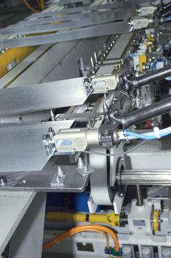
Because of the sweeping trajectories in triaxis transfer press part handling, the workpiece typically must be secured with pneumatic grippers and shovels rather than suction cups.
Given today's focus on productivity and competitive pricing, it's no surprise that the goal of stamping operations is to achieve the highest net yields at the lowest cost. More good parts out the door translates into more profit. And given that press lines are at the front of most other assembly operations, a lag in the pressroom can drag the rest of the operation downhill.
No company can afford to have expensive press line equipment running at less than its peak production rate. Ironically, the automation's part-holding tooling—a fraction of the total press line cost—often is the reason that stamping operations do not run at full potential.
Taking the correct approach to tooling up the automation on a press line can make all the difference.
First and most important, involve your tooling and automation supplier early in the process—during die design. At this stage the supplier can provide useful and necessary insight, so that obstacles and opportunities can be realized before implementation.
Involving your automation equipment supplier at this point will greatly reduce the amount of time it takes to launch production and can cut costs substantially.
It really pays to simulate the processes virtually. This is particularly true for triaxis transfer press lines, in which press speed must be optimized for multiple motion paths, without any interferences. Typically, you propose the process and provide the supplier with the part data. The die designer is responsible for developing the die around those curves.
With simulation software, you can determine the production rate of any line by proposing the best trajectory for the operation (see Figure 1). You also can identify potential collisions in the virtual world, eliminating retooling or reprogramming late in the production cycle.
Uncovering potential collisions with a die in a stamping press before production starts allows the diemaker to modify the design before production, saving hours of work (and downtime) later to mill the die down to size.
The next decision you'll need to make involves the tooling framework. Components such as brackets, clamps, and connectors are attached to this framework to secure the suction cups, grippers, shovels, and magnets that are used to handle workpieces.
The material for the tool frame is an important consideration. With a focus on press strokes per minute, the goal is to make the tool framework as light as possible, yet durable enough for the application at hand.
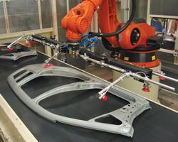
Figure 2: Press operations can benefit from carbon fiber booms, which reduce the frame weight up to 50 percent compared to steel and aluminum tubing.
Triaxis press tooling framework typically is made of steel, while tandem lines often employ aluminum extrusions for the framework. The aluminum provides long life, low maintenance, and repeatability of the robot motion. However, as part size increases, so does the amount of tooling, as more suction cups are required to hold the sheet metal. Larger tooling can get heavy and cause a vibration or harmonics issue, interfering with the robot's ability to settle quickly and accurately into position.
Carbon fiber (Cf) frame components can help to prevent vibration (see Figure 2). A Cf frame can weigh up to 50 percent less than aluminum while exhibiting less deflection. It also enables faster motion paths and quicker settling of the robot. In some cases, stampers have achieved productivity increases of up to 20 percent after equipping robots with Cf booms.
Your choice of end-of-arm tooling will be influenced by the press operation; the trajectory and weight limits of the automation best determine how to secure the workpiece.
Vacuum Cups. For tandem press operations, which typically involve an up-and-down motion or a back-and-forth motion, suction cups are a good choice, as it is easy to create a vacuum to hold the part (see Figure 3). The cups come in several shapes, cleat designs, and materials.
Bell-shaped cups typically can't be used for applications that involve a trajectory that dives into the part, but they are suitable for straight up-and-down motions, such as destackers. With sweeping approaches to the part it is better to use a flat-style cup, which can work with flat parts that are smooth or slightly textured.
For thicker sheet metals, choose a cup with a cleated pattern close to the center. This provides more support and prevents the vacuum from drawing or dimpling the panel. For thinner panels, the cleat design should be more evenly distributed across the whole surface of the cup, dispersing the suction equally to prevent unusual gripping or dimpling.
Bellows cups are flexible and so can accommodate uneven and moderately contoured parts while holding during acceleration and deceleration. They are suitable for light oil and duty. Traction cups are less flexibile on uneven or contoured parts, but secure the part better during acceleration and deceleration. They are suitable for destackers and feeders systems. Flatfoot cups have the best shear holding force during part acceleration and deceleration. They can be used on Class A surfaces that are oily or sensitive to dimpling.
The goal is to use the minimum number of cups per operation. Cups typically are spaced 9 to 12 inches apart for material handling in blanking operations. Use this formula to calculate how much vacuum you will need to lift the panel:
Lifting capacity = 0.4912 × C × P
F(4)
where:
C = area of vacuum pad surface (in square inches)
P = amount of vacuum (in inches of mercury)
F = safety factor
Grippers and Shovels. Triaxis transfer presses typically employ multiaxis transfer systems, which often use a sweeping motion to approach the part and secure it for material handling. In addition, the shapes and sizes of parts in these applications usually do not lend themselves well to vacuum cups. For these applications, part grippers are most suitable.
In some transfer press situations, the part can be moved at an optimum rate of speed using shovels instead of grippers. Shovels cost less and require less maintenance than grippers, but they are limited in use to sheet metal components that have some stability. Typically, the first operation on any transfer press line requires grippers because the part is flexible and weak. That first stamping operation gives the part some shape and stability, allowing the use of shovels or a combination of shovels and grippers.
Your automation supplier's responsibility is to help you get the press line optimized through the implementation of the right tooling and components. Working with your supplier early in the process to make the most suitable choices for your application.


The Fabricator is North America's leading magazine for the metal forming and fabricating industry. The magazine delivers the news, technical articles, and case histories that enable fabricators to do their jobs more efficiently. The Fabricator has served the industry since 1970.
start your free subscription
Easily access valuable industry resources now with full access to the digital edition of The Fabricator.

Easily access valuable industry resources now with full access to the digital edition of The Welder.

Easily access valuable industry resources now with full access to the digital edition of The Tube and Pipe Journal.

Easily access valuable industry resources now with full access to the digital edition of The Fabricator en Español.
In this episode of The Fabricator Podcast, Caleb Chamberlain, co-founder and CEO of OSH Cut, discusses his company’s...


