


A closer look at self-piercing riveting
Computer simulation is a noteworthy alternative to physical testing of joints
The current vehicle market demands structural weight reduction to decrease fuel consumption and to improve vehicle performance. As a result, automotive manufacturers are required to use aluminum alloys and other advanced materials, but the conventional joining methods, such as resistance spot welding (RSW), can be inadequate for use on many of these materials.
One alternative for such applications is self-piercing riveting (SPR). It can join aluminum alloys, prepainted materials, and different material combinations that are difficult or unsuitable to weld. Unlike RSW, no metallurgical process is involved in SPR joining. In addition, SPR equipment and tools do not require as much maintenance as RSW equipment, and SPR does not require the preliminary hole-making and alignment needed with conventional riveting.1,2,3
The SPR process and SPR joints appear worthy of further study, and finite element analysis (FEA) is an appropriate tool to do just that. FEA can display the result visually without a physical test.
What Is SPR?
As a sheet joining method, self-piercing riveting is a large-deformation process that involves piercing. The self-piercing rivet, under the press from the punch, pierces the top sheet and forms a mechanical interlock with the bottom sheet. The process comprises many pairs of contacts between the punch, holder, rivet, top sheet, bottom sheet, and die.
Aluminum alloy AA5754 often is used for body structures and reinforcements in the automotive industry. Therefore, AA5754 was chosen as the sheet material in the study. The chemical composition and mechanical properties of AA5754 can be found in Alcan Automotive Product Data Sheet.4The sheet thicknesses were 1 mm and 2 mm.
Simulation of the SPR Process
The nonlinear finite element model was used because the geometries of the parts and their materials are nonlinear. The contacts and friction produced by the SPR system provided another reason for using this model.
The punch, holder, and die were treated as rigid bodies. The self-piercing rivet, top sheet, and bottom sheet were treated as deformable bodies. During the SPR process, the holder and die held the two sheets.
 |
| Figure 1 FEM of the SPR Process |
Six pairs of contacts exist in this self-piercing process. The self-piercing rivet contacts both sheets at rivet bottom, inside the rivet's semitubular shank and outside the rivet's semitubular shank. The six pairs of contacts are between the punch and rivet, blank holder and top sheet, rivet and top sheet, rivet and bottom sheet, top sheet and bottom sheet, and bottom sheet and die. Friction exists between all the contact pairs. Based on previous research, 0.1 was chosen as the friction coefficient.
The material model used in the FEA was elastic-plastic because a large amount of plastic deformation is characteristic of the SPR process and needs to be a part of any analysis.
When analyzing large plastic deformation, researchers must consider strain hardening. Both the sheet material and rivet material were assumed to be isotropic in strength and in hardening. True stress and true strain were used in the study because the SPR process is a plastic deformation problem.
The true (Cauchy) stress and strain were used during the plastic deformation in the numerical analysis. A piecewise linear model—which is made up of two or more linear models—was used.
The self-piercing rivet material was boron steel SAE 10B35. Boron can increase material hardenability without loss of ductility. The only available material property of SAE 10B35 was its hardness—480 Vickers hardness (HV), ±30 HV. Other properties could not be found even in the Metals Handbook.5
A Vickers hardness has an equivalent value of a Brinell hardness.6On the basis of the relationship between material hardness and strength,7the yield strength and the ultimate tensile strength could be calculated. The piecewise linear model was used for the true stress or, in other words, the true strain relationship of material SAE 10B35.
The four-noded quadrilateral 2-D element was used in the numerical analysis. The chosen element type 10 corresponded to full integration for large-deformation problems. The remeshing element was set when element distortions were large. The contact relationships were defined in the analysis to indicate the contacts between the components of the system.
Simulation was also used to examine different yield strengths of self-piercing rivet materials. When the yield strength of a self-piercing rivet material was too low, the self-piercing rivet deformed before it could pierce the top sheet. If the yield strength of the self-piercing rivet material was too high, the self-piercing rivet could not deform, so it could not form an interlock with the sheets.
The Simulation Result
Figure 1shows the FEM model for the SPR process. The sheets were first held together by the blank holder and die.
 |  |  |
| Figure 2 SPR Rivet Touches Top Sheet | Figure 3 SPR Rivet Begins to Pierce Top Sheet | Figure 4 SPR Rivet Pierces Top Sheet Halfway |
The simulation, shown in Figures 2-6, revealed the self-piercing rivet touching the top sheet, piercing the top sheet, and forming an interlock with the bottom sheet at the conclusion of the process. The punch then went back to the starting point.
 |  |
| Figure 5 SPR Rivet Finishes Piercing Top Sheet | Figure 6 SPR Process Concludes |
The residual stress distribution in the sheets and the rivet after SPR could be simulated as well. Principal stress and equivalent stress were used to express the residual stress in the sheets and the self-piercing rivet. Figure 7shows the distribution of the maximum stress component of the principal stresses. Figure 8shows the distribution of the equivalent von Mises stress. Figure 9shows the total equivalent plastic strain, in which the maximum value of the strain occurs at the bottom sheet formed by the die.
 |  |  |
| Figure 7 Maximum Component of Principal Stress | Figure 8 Equivalent von Mises Stress | Figure 9 Total Equivalent Plastic Strain |
A New Method for Predicting Physical Attributes
Physical attributes of SPR joints are used in industry empirically to assess the quality of an SPR joint. The physical attributes are part of the criteria used to determine whether an SPR joint is acceptable.
Three physical attributes are used to evaluate the quality of SPR joints. They are bottom thickness, undercut, and spread. The physical attributes can be obtained by measuring the axial section of an SPR joint, as shown in Figure 10.
Bottom thickness is the vertical distance between the rivet foot bottom and the interface of the bottom sheet and the die's cavity. Undercut is the horizontal distance between the outside of the rivet foot and the point where the rivet has completely pierced through the top layers of sheets. The point can be identified by finding the interface between the two layers (two bottom layers if there are more than two layers total) and the rivet shank. Spread is the horizontal distance of the deformed rivet foot relative to the rivet shank, which should not have any deformation. Spread shows how much the rivet has flared in the joint.8
When the physical attributes are obtained by a mechanical testing method, five pieces of equipment are needed: a self-piercing riveter, an abrasive cutter, a sample mounting device, a grinding machine, and a digital microscopic measuring device. With this type of conventional testing method, the section of the SPR joint obtained must go through the joint axis to obtain the physical attributes of the SPR joint.
However, evaluating the physical attributes of SPR joints through the finite element method is now a reasonable alternative to the conventional method of testing. The physical attributes can be analyzed from the deformation of the SPR joint section obtained via computer simulation.
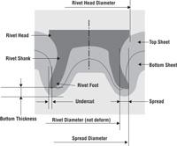 | 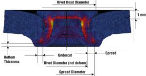 |
| Figure 10 Schematic Diagram of Physical Attributes of Self-piercing Riveted Joint | Figure 11 Physical Attributes of Self-piercing Riveted Joint From Computer Simulation |
Figure 11shows the physical attributes of an SPR joint from computer simulation. From the observation of the physical attributes, it can be determined whether the three physical attributes meet the industrial visual check criteria.
Simulation and SPR
Computer simulation can aid the SPR process as follows:
- The deformations of the self-piercing rivet and the sheets can be seen in detail during the process.
- While the distribution of the residual stress still can be obtained from the numerical analysis, the location of the maximum stress can be observed with computer simulation.
- With FEM, the physical attributes of an SPR joint can be examined and a decision made whether the SPR joint is acceptable.
Simulation also is useful for observing metal flow.
Yingjie Xu conducted this research as a doctoral student at the Department of Mechanical, Industrial, and Manufacturing Engineering, University of Toledo.
Notes
- Training Documents for Self-Piercing Riveting Systems, Emhart Fastening Teknologies, 2002.
- L. Fendrick and D.M. Reeve, "Assembly Solutions With Fastriv® Self Piercing Systems," Mechanical Fastening Seminar, Troy, Mich., Jan. 27, 1998.
- N. Bokhari and M. LaPensee, "Self-Piercing Riveting in Automotive Applications," Mechanical Fastening Seminar, Troy, Mich., Jan. 27, 1998.
- Alcan Automotive Product Data Sheet, Alloy AA5754/HS5754, Alcan Automotive Corp., October 2001.
- Metals Handbook, American Society for Metals, 2000.
- ASM Metals Reference Book, 2nd edition, American Society for Metals, 1983.
- S. Kalpakjian, Manufacturing Processes for Engineering Materials, 3rd edition, Addison-Wesley Longman Inc., 1997.
- Training Documents for Self-Piercing Riveting Systems, Emhart Fastening Teknologies, 2002.
About the Author
About the Publication
subscribe now

The Fabricator is North America's leading magazine for the metal forming and fabricating industry. The magazine delivers the news, technical articles, and case histories that enable fabricators to do their jobs more efficiently. The Fabricator has served the industry since 1970.
start your free subscription- Stay connected from anywhere

Easily access valuable industry resources now with full access to the digital edition of The Fabricator.

Easily access valuable industry resources now with full access to the digital edition of The Welder.

Easily access valuable industry resources now with full access to the digital edition of The Tube and Pipe Journal.

Easily access valuable industry resources now with full access to the digital edition of The Fabricator en Español.
- Podcasting

In this episode of The Fabricator Podcast, Caleb Chamberlain, co-founder and CEO of OSH Cut, discusses his company’s...
- Trending Articles
1
AI, machine learning, and the future of metal fabrication

2
Employee ownership: The best way to ensure engagement

3
Steel industry reacts to Nucor’s new weekly published HRC price

4
How to set a press brake backgauge manually

5
Capturing, recording equipment inspection data for FMEA
