


Contributing Editor
Gap, or C-frame, mechanical stamping presses have undergone relatively few fundamental design changes since they were first introduced in the mid-1800s. The basic principle behind their operation, simply stated, is this: Inertial energy stored in a rotating flywheel is converted to a reciprocating (up-and-down) motion, which provides the power for tooling to punch, blank, bend, draw, or perform some other value-added process to a workpiece.
More recently, however, changes in tooling technologies, material specifications, part quality requirements, and inventory levels have driven the demand for new developments in the way a mechanical press operates.
While the requirements for good tooling design, proper maintenance, and well-trained operators are as important as always, recent innovations such as link motion and bridge-frame structure are helping metal stampers achieve in smaller gap-frame presses the performance and production levels typically reserved for large straight-side machines.
To improve workpiece quality while speeding production and lowering per-part costs, mechanical press builders have sought to combine the high production rates of a mechanical press with the slower working speed of a hydraulic press. For the past several decades they have accomplished this by applying link motion technology to large-capacity machines of several hundred tons.
Today, gap-frame press manufacturers are introducing a new generation of low-tonnage link motion presses that feature highly rigid frames, bringing large-press performance and productivity to smaller machines.
In a link motion press, the velocity of the slide is slowed during the working portion of the stroke, with the tonnage, torque, and flywheel energy — the three factors of true press capacity — remaining constant. By comparison, if the flywheel of a crank motion press is slowed below its rated speed by even 30 percent to improve material flow and yield a higher-quality part, about 50 percent of available tonnage, torque, and flywheel energy is lost.
Equally important is the point in the stroke at which that reduction in slide velocity occurs. Slide speed requirements are different for a press used for progressive blanking and shallow forming and a press used for deep drawing. A generic link motion curve that is designed to suit as many applications as possible is likely to provide less than optimum performance in some situations. A better alternative can be a link motion curve designed to meet the specific needs of an application, such as progressive work or deep drawing (see Figure 1).
Link motion uses a mechanical assembly installed in the press's gear transmission. The link mechanism accelerates the downward travel of the slide, then slows it during the working portion of the stroke, with the tonnage, torque, and flywheel energy remaining constant. The speed is again accelerated for a fast retract to the top of the stroke.
In contrast, the slide of a crank motion press maintains the same velocity throughout the full stroke travel. Nearly all presses in the U.S. less than 200 tons' capacity are crank motion-type machines.
Material flows better in tooling when slide velocity is reduced. And, because the material is held in the working portion of the stroke for a longer period of time, dimensional tolerances can be improved because springback is reduced or eliminated. In deep-draw applications, tearing and wrinkling are minimized.
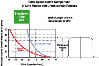
Figure 1A generic link motion curve designed for many applications can produce less than optimum performance in some situations. As an alternative, a link motion curve designed for a specific application, such as progressive blanking or deep drawing, can be helpful.
Because the operating speed of the tooling is reduced, the accompanying friction also is reduced. Less friction results in less heat, which helps to increase tooling life. Punches also break less at lower impact speeds.
Link motion also helps to reduce noise (in decibels and pitch) and vibration produced during pressworking. This can be important in blanking applications that have large reverse loading (or snap-through) forces.
Frame deflection is one of the main reasons that gap-frame presses often cannot run high-precision jobs, particularly those that use close-tolerance tooling. If deflection can be held within acceptable parameters, many jobs formerly run in larger straight-side machines can be moved to more compact gap-frame machines.
For decades, tie rods were installed to control gap-frame press deflection. To work properly, tie rods have to be tightened to the point that preload is put on the press frame. This can cause the press slide and bolster to be in an out-of-parallel condition.Rather than using tie rods and spacers, some manufacturers now employ a rigid structure, called a bridge-frame structure, to help control deflection in critical applications.
Massive, solid steel beams are precision-machined and fitted to the individual press frame. This precise fit and strength help the press to resist deflection (gap opening), as well as other types of distortion, without putting preload stress on the frame. With no tie-rod adjustments needed, performance can be consistent and repeatable.
When properly engineered and installed, the bridge-frame structure can help bring gap-press performance levels close to those of a high-quality straight-side press. Frame deflection typically is reduced by 60 percent or more. Tooling interference — and the noise it generates — is reduced, which helps to extend tooling life between sharpenings and to reduce punch breakage.


The Fabricator is North America's leading magazine for the metal forming and fabricating industry. The magazine delivers the news, technical articles, and case histories that enable fabricators to do their jobs more efficiently. The Fabricator has served the industry since 1970.
start your free subscription
Easily access valuable industry resources now with full access to the digital edition of The Fabricator.

Easily access valuable industry resources now with full access to the digital edition of The Welder.

Easily access valuable industry resources now with full access to the digital edition of The Tube and Pipe Journal.

Easily access valuable industry resources now with full access to the digital edition of The Fabricator en Español.
In this episode of The Fabricator Podcast, Caleb Chamberlain, co-founder and CEO of OSH Cut, discusses his company’s...


