Graduate Research Assistant, ERC/NSM
- FMA
- The Fabricator
- FABTECH
- Canadian Metalworking
Categories
- Additive Manufacturing
- Aluminum Welding
- Arc Welding
- Assembly and Joining
- Automation and Robotics
- Bending and Forming
- Consumables
- Cutting and Weld Prep
- Electric Vehicles
- En Español
- Finishing
- Hydroforming
- Laser Cutting
- Laser Welding
- Machining
- Manufacturing Software
- Materials Handling
- Metals/Materials
- Oxyfuel Cutting
- Plasma Cutting
- Power Tools
- Punching and Other Holemaking
- Roll Forming
- Safety
- Sawing
- Shearing
- Shop Management
- Testing and Measuring
- Tube and Pipe Fabrication
- Tube and Pipe Production
- Waterjet Cutting
Industry Directory
Webcasts
Podcasts
FAB 40
Advertise
Subscribe
Account Login
Search
Blanking developments - Part II
Fineblanking part, process design
- By Serhat Kaya and Taylan Altan, Ph.D.
- August 8, 2007
- Article
- Bending and Forming
Editor's Note: This is Part II of a three-part series on blanking developments. Part I focuses on fineblanking and tool design. Part III covers high-speed blanking and finite element analysis.
This column was prepared by Serhat Kaya, the Center for Precision Forming (CPF, formerly ERC for Net Shape Manufacturing), The Ohio State University, Taylan Altan, professor and director.
The automotive industry is increasingly accepting fineblanking in its various forms to produce sheet metal components with smooth edges that don't require additional finishing operations.
Press Ram Travel
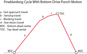
A typical fineblanking ram cycle is shown in Figure 1. From the bottom dead center (BDC) where the tool is fully open, the ram moves up at a fast travel speed as far as a preset tool gap. Ram speed is reduced at point b to allow a sensing operation. It then begins its blanking travel per second (c) at a lower speed. Blanking speed is important and can be varied between 5 and 50 mm/s based on the material. At top dead center (TDC), blanking is complete and the ram returns rapidly to BDC (d).
Part Design
Fineblanked parts require a high cut surface quality, close dimensional tolerances, and flatness. A part's geometric shape, sheet metal thickness, and material characteristics determine if fineblanking is possible. Part features such as slot width, section width, hole diameters, tooth forms, corner angles, and radius determine how difficult it will be to blank the part. Extremely small holes with a blank-thickness-to-hole-diameter ratio of about 2 also can be fineblanked without any major problems.
Dimensional, Form Tolerances
Achievable part tolerances depend on the material, workpiece thickness, and geometric shape. The blanking press, die, and lubricant also are significant in determining achievable part quality. For example, die-roll width depends on die-roll height. Cut surfaces are not absolute right angles to the plane of the sheet metal. The blank's outside contours on the burr side are greater than at the die-roll side. A guideline is the difference amounts to 0.0026 mm per 1 mm of blank thickness and depends on a number of influencing variables.
Tool Design Parameters
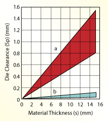
Die Clearance. In conventional blanking and fineblanking processes, die clearance is one of the most important process parameters because it affects sheared surface quality. In practice, die clearance is expressed as a percentage, the ratio of clearance length (one side only) to sheet thickness. A clearance value between 5 and 10 percent is used in conventional blanking, whereas 0.5 percent clearance is more common for fineblanking. Figure 2 shows the change in die clearance with changing material thickness.
Vee-Ring Dimensions. A significant fineblanking tool feature is Vee-ring dimension. Its function is to hold the punched material under compressive stresses. Vee-rings can be located either on the guide plate or the die plate or on both. Material thickness dictates if a single Vee-ring or two Vee-rings, one on the guide plate and the other on the die plate, are necessary. Vee-ring dimensions and the distance from the blanking edge depend on sheet metal thickness.
Figure 3 shows the geometric guidelines for a Vee-ring design located on the upper die plate.
About the Authors
Serhat Kaya
1971 Neil Ave. Baker Systems Engineering, Room 339
Columbus, OH 43210
614-292-9267

Taylan Altan, Ph.D.
Professor Emeritus and Director - Center for Precision Forming
subscribe now

The Fabricator is North America's leading magazine for the metal forming and fabricating industry. The magazine delivers the news, technical articles, and case histories that enable fabricators to do their jobs more efficiently. The Fabricator has served the industry since 1970.
start your free subscription- Stay connected from anywhere

Easily access valuable industry resources now with full access to the digital edition of The Fabricator.

Easily access valuable industry resources now with full access to the digital edition of The Welder.

Easily access valuable industry resources now with full access to the digital edition of The Tube and Pipe Journal.
- Podcasting
- Podcast:
- The Fabricator Podcast
- Published:
- 04/16/2024
- Running Time:
- 63:29
In this episode of The Fabricator Podcast, Caleb Chamberlain, co-founder and CEO of OSH Cut, discusses his company’s...
- Industry Events
16th Annual Safety Conference
- April 30 - May 1, 2024
- Elgin,
Pipe and Tube Conference
- May 21 - 22, 2024
- Omaha, NE
World-Class Roll Forming Workshop
- June 5 - 6, 2024
- Louisville, KY
Advanced Laser Application Workshop
- June 25 - 27, 2024
- Novi, MI


