


Contributing Writer
 |
| Figure 1 |
First let's talk basics. Cams mechanically transfer vertical ram motion and force into horizontal or semihorizontal motion and force. Because cams often are used for cutting when precision alignment is critical, they must have a good guidance system. Second, because they are subjected to a great deal of motion, friction, and force, they must be designed and manufactured to withstand the natural wear and tear that occurs over thousands or even millions of cycles. Here are some guidelines for cam design. Refer to Figure 1 as you read about each of the design features.
1. Use dissimilar metals for die sections that interface.
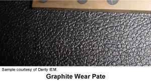 |
| Figure 2 |
Avoid using tool steels that are metallurgically the same for both the cam and the driver. Doing so can cause severe friction, which produces heat. Excessive heat can cause cold welding or adhesive galling of both the cam slide and the driver. Excessive heat buildup also causes thermal expansion of the cam. This expansion can make the cam slide freeze up.
Aluminum bronze, also known as Ampco® bronze, is a fine material to use for cam slide drivers and wear plates. It can be purchased with graphite plugs to make them lubeless. Figure 2 shows a graphite inserted plate. Note: Avoid using heavy grease or oil on these types of wear plates because these substances create suction that can pull out the graphite. Use light oil only. Consult your tool steel specialist if you are unsure of your tool steel interface compatibility.
2. Whenever possible, bypass the entire wear surface with the cam slide.
 |
| Figure 3 |
Not fully bypassing the wear surface can create a tiny groove in the wear plate. If the cam overtravels and hits this tiny bump, cam jump can occur. In simple terms, it's like hitting a speed bump in your car. If you are traveling at a great rate of speed, your car will rise considerably higher than the bump. In a cam slide, this action can break or shear the cutting punch or sections. Bypassing the entire wear plate promotes even wear.
3. Extend the cam slide as close as you can to the punch point/cutting edge.
Remember that a cutting cam's function is to provide precision alignment. Extending the cam closer to the punch point or cutting edge allows the control point to be moved closer to the cutting edge. In other words, imagine holding a broom stick by its end. Moving your hands just a little allows the broom to move a lot on the opposite end. However, holding it in the middle and moving your hand the same amount decreases the amount of movement at the opposite end. Extending the cam closer to the punch point permits gibbing to be used closer to the punch point.
4. Use a special tapered matrix for cam piercing.
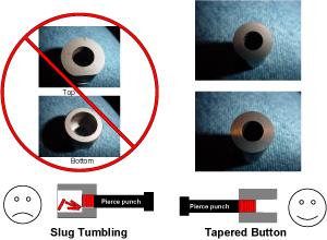
 |
| Figure 4 |
Avoid using a button or matrix that allows the slug to tip or fall over in it. Make sure that the matrix has a very slight taper to enable the slugs to move freely, but not allow them to tip over. Slugs that tip over can tumble and jam up inside the matrix. This could cause the button or matrix to explode in severe compression.
Never use a "sudden death" or relief slug drop-type button. Although these buttons are fully acceptable for conventional, direct piercing, they allow the slugs to tip over when installed horizontally. See Figure 3.
5. Use a slug shedder.
Use a special angled slug shedder made from hardened tool steel to force the slugs downward in the die. This insert can be screwed to the top of the block that holds the button.
 |
| Figure 5 |
Aerial cams commonly are used for piercing on angular surfaces. However, aerial cams differ from standard cams in that the moving cam slide assembly is mounted on the top die shoe rather than on the bottom die shoe. This positioning allows the entire cam slide to travel up with the ram without interfering with transfer fingers and systems. Aerial cams also allow hole piercing at virtually any angle. Figure 4 shows a typical aerial cam design. The same basic design rules apply.
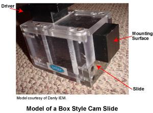
Box cams can be custom-made; however, most are commercially purchased. Box cams are a great alternative to standard cams and provide excellent guidance. The cam slide is precision-ground square and accurately guided by a surrounding box ground to fit the slide. Box cams have a positive-return feature that forces the cam to retract if the return spring accidentally breaks. They can be drilled for punch and die section mounting. See Figure 5.
 |
| Figure 6 |
Lever cams use a specially shaped lever to transfer force. A special design provides a positive cam return. Because they are small, lever cams commonly are used for small punching and piercing operations. They can be placed in confined spaces. However, most models cannot be mounted on severely angular surfaces. See Figure 6.
 |
| Figure 7 |
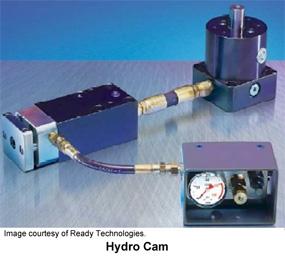
Hydro cams are popular when die space is at a premium. These cams allow for the driving cylinder to be mounted a fair distance away from the slide, enabling the cam slide to be placed in an extremely confined space. Because the slide is activated hydraulically, the cams are not position-sensitive; they can be installed in any position. Hydro cams are a good alternative to conventional cam piercing. See Figure 7.
Although positive returns can function to pull back cam slides if the spring breaks, they are not intended for long-term usage. Periodically check cam return springs and lubricate cams as needed.
When purchasing a cam, look closely at the fundamental guidelines provided at the beginning of this article. Avoid purchasing cams made with poor tool steel or poor assembly and fit. Consult with your supplier to see what cam best suits your operations.


The Fabricator is North America's leading magazine for the metal forming and fabricating industry. The magazine delivers the news, technical articles, and case histories that enable fabricators to do their jobs more efficiently. The Fabricator has served the industry since 1970.
start your free subscription
Easily access valuable industry resources now with full access to the digital edition of The Fabricator.

Easily access valuable industry resources now with full access to the digital edition of The Welder.

Easily access valuable industry resources now with full access to the digital edition of The Tube and Pipe Journal.

Easily access valuable industry resources now with full access to the digital edition of The Fabricator en Español.
In this episode of The Fabricator Podcast, Caleb Chamberlain, co-founder and CEO of OSH Cut, discusses his company’s...


