Contributing Writer
- FMA
- The Fabricator
- FABTECH
- Canadian Metalworking
Categories
- Additive Manufacturing
- Aluminum Welding
- Arc Welding
- Assembly and Joining
- Automation and Robotics
- Bending and Forming
- Consumables
- Cutting and Weld Prep
- Electric Vehicles
- En Español
- Finishing
- Hydroforming
- Laser Cutting
- Laser Welding
- Machining
- Manufacturing Software
- Materials Handling
- Metals/Materials
- Oxyfuel Cutting
- Plasma Cutting
- Power Tools
- Punching and Other Holemaking
- Roll Forming
- Safety
- Sawing
- Shearing
- Shop Management
- Testing and Measuring
- Tube and Pipe Fabrication
- Tube and Pipe Production
- Waterjet Cutting
Industry Directory
Webcasts
Podcasts
FAB 40
Advertise
Subscribe
Account Login
Search
Demystifying die protection
Sensors and controls: eyes and brain of die protection
- By Greg Dickerson
- November 1, 2010
- Article
- Bending and Forming
Technology is rapidly changing lives and how people live. Most days they leave the house and go to work without noticing that anything differs that day from the day before or even the week before. But every day the world changes. It may be gradual and subtle, but change is constant and unstoppable.
One of the best examples of this is the evolution of cell phones. These days everyone has a cell phone and many people have more than one.
The first hand-held phones on the market were bulky and had a short battery life. Service was restricted to major cities and highways. Cell phones evolved and now can be used as movie cameras, to access the Internet, send text messages, do daily planning, alert with alarms—and the list goes on and on.
The point is that as dependence on electronic technology increases, stampers must stay current and use the technology that is available.
Questions to Ask About Die Protection
In considering how technology may improve your operations, you may start by asking some questions. The first question to ask is, what is the industry standard? In other words, what is the competition doing? The answer is likely that they are using die protection.
The second question to ask might be, what can I do that other stampers cannot? Some stampers can perform 100 percent inspection on critical dimensions. By doing so, they can set control limits to detect when a process is starting to go out of control before they produce bad parts, thus eliminating defective parts and the need for rework. With vision systems becoming more user-friendly, many progressive stampers are integrating cameras into their stamping processes to gain even more of a competitive edge over their competition.
Like almost everything else, embracing new technology starts with becoming familiar with the basics. Die protection is no different.
So, what is die protection? Originally die protection was developed just to prevent damage to the tool and die during the operation of a stamping press. As sensor and controls technology has evolved and stampers’ knowledge of it has increased, die protection technology has been expanded into other applications, such as raising production rates and performing quality assurance.
In some cases, die protection technology has allowed die builders to create very intricate dies that were impractical to manufacture before because they were vulnerable to die crashes. As a result, some of the more intricate dies allow stampers to form components in one stage that would have required two or more operations, thereby eliminating some secondary operations.
So what comprises die protection? Die protection has two main components: sensors and controls. Sensors are the “eyes” of the die protection system; they detect what is going on in the die. Controls can be described as the brains of die protection.
Sensors
Sensors are looking for events to happen in the die. For instance, a sensor might be looking for material to feed or for a part to eject from the die.
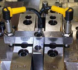
Although many types of electronic sensors are available, two are most commonly used for basic die protection. They are inductive proximity sensors, commonly known as proxes, and photoelectric sensors, or photo-eyes.
Analog and Digital Sensors. Basic analog sensors use a discrete signal. This simply means that the sensor is on or off, like a light switch.
Digital sensors use a variable signal. A digital sensor might use 0 to 10 volts of direct current to indicate how close or far an object is from the sensor face. Digital sensors are used for in-die measurement.
Inductive Proximity Sensors. Inductive proximity sensors operate on the principle of converting electricity into a magnetic field. The best way to describe this may be the old science experiment in which a nail, battery, and wire are used to create an electromagnet. Wrapping the wire around the nail and then connecting the wire ends to the positive and negative terminals of the battery magnetizes the nail.
Inductive proximity sensors use electricity to create a magnetic field to detect metal objects. They do not have a long range, and so often they are used with a mechanical apparatus that will allow an object to be detected at further distances and in more difficult applications.
Inductive proximity sensors come in a variety of sizes and shapes. Cylindrical inductive proximity sensors are measured by their diameter and length. Generally, the larger the sensor’s diameter, the greater its range. Cylindrical sensors come with either a threaded or smooth bore body type for various mounting approaches. They also come in what is called block-type bodies. Catalogs are full of shapes and sizes to accommodate the many applications they will be used in.
Photoelectric Sensors. Photoelectric sensors send out and detect light. There are many types of these sensors on the market. Three types are used for the bulk of basic die protection—diffuse-reflective, retro-reflective, and through-beam. They are differentiated by their function.
A diffuse-reflective photoelectric sensor emits light that reflects off of an object and is then relayed to the sensor’s receiver. Its light emitter and receiver are together on the same sensor head.
A retro-reflective photoelectric sensor’s emitter and receiver are mounted on the same sensor head also, but it has an additional reflective device. When an object passes between the sensor head and the reflective device, the sensor is activated.
The through-beam photoelectric sensor’s emitter and receiver are mounted separately. The light is sent from the emitter sensor head and is detected by the receiver sensor head. Like the retro-reflective photoelectric sensor, this sensor detects an object when it breaks a light beam.
Photoelectric sensors generally have a longer range than inductive proximity sensors.
Controls
The control is what can be considered the brains of a die protection system. The control collects information from the sensors (the discrete electronic current) and resolver (some systems use an encoder, but both serve the same function). The resolver or encoder ensures that everything is functioning properly.
The resolver is a device that is mounted directly to or mechanically connected to the press’s crankshaft. The resolver continually measures the position of the ram during the press cycle. A press cycle is measured in degrees. One revolution of the press’s crankshaft is one press cycle, which is equal to 360 degrees.
Two types of die protection programs are cyclic events and static events. A cyclic event occurs during the press cycle. Examples are stock strip feeding forward in a progressive die or a finished piece part exiting the die in the parting station. Anything that must happen at a specific time for a die to function properly would use a cyclic program.
A static event is something that must always happen—or should never happen—regardless of where the press is in the press cycle, such as the material feeding into the die from the decoiler and straightener. If the material runs completely out, a short feed can occur as the material is pulled back after it has been fed to the correct length.
Let’s look at how die protection could be applied to a typical material feed application. A sensor is placed at the end of a progressive die to detect when the stock strip has been fully advanced. The control is programmed to look for a signal from the sensor at a specific window of time that is programmed in degrees. As long as the control sees a signal from the sensor during the timing window, the press will continue cycling and producing parts. If the control does not see a signal from the sensor in the designated timing window (meaning that the material has failed to advance to the correct location), the control will then interpret the lack of signal at the appointed time as a misfeed. The control then signals the press to stop before the die is damaged.
Controls can be programmed to detect not only misfeeds, but also part ejection, slug ejection, or a broken punch that is no longer piercing a hole in the finished part.
Just like cell phones, GPS, computers, and other electronic devices, die protection continues to evolve with stronger sensors and more user-friendly controls with greater capabilities.
About the Author
subscribe now

The Fabricator is North America's leading magazine for the metal forming and fabricating industry. The magazine delivers the news, technical articles, and case histories that enable fabricators to do their jobs more efficiently. The Fabricator has served the industry since 1970.
start your free subscription- Stay connected from anywhere

Easily access valuable industry resources now with full access to the digital edition of The Fabricator.

Easily access valuable industry resources now with full access to the digital edition of The Welder.

Easily access valuable industry resources now with full access to the digital edition of The Tube and Pipe Journal.
- Podcasting
- Podcast:
- The Fabricator Podcast
- Published:
- 04/16/2024
- Running Time:
- 63:29
In this episode of The Fabricator Podcast, Caleb Chamberlain, co-founder and CEO of OSH Cut, discusses his company’s...
- Industry Events
16th Annual Safety Conference
- April 30 - May 1, 2024
- Elgin,
Pipe and Tube Conference
- May 21 - 22, 2024
- Omaha, NE
World-Class Roll Forming Workshop
- June 5 - 6, 2024
- Louisville, KY
Advanced Laser Application Workshop
- June 25 - 27, 2024
- Novi, MI


