


Professor Emeritus and Director - Center for Precision Forming
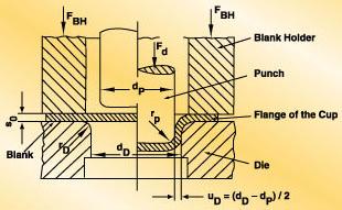 |
| Figure 1: Addendum types enable or improve the stamping of a sheet metal part. A draw wall, for example, connects the trim line and the punch opening line. |
Editor's Note: This column was prepared by the staff of the Engineering Research Center for Net Shape Manufacturing (ERC/ NSM), The Ohio State University, Professor Taylan Altan, director. It is the second of a two-part series on the topic of stamping of aluminum alloys. The first part was published in the May/June issue and discussed part design considerations and practical part and tooling design rules. This issue's article covers addendum design methodology for improving the formability of aluminum stampings.
Addendum types are additional die features that enable or improve the stamping of a sheet metal part. They usually are located inside the punch opening line (die contour) but outside of the trimming line (seeFigure 1). They are removed by the trimming operation.
Addendums serve three purposes:
1. They are necessary for their transition features depending on the chosen blank holder design.
2. They help prevent wrinkling and tearing.
3. They facilitate subsequent process steps, such as flanging.
Addendum types should be used only when absolutely necessary. The decision to use them is made by the designers and the tryout experts, who usually base their decision on experience.
Commonly used addendum types are draw walls, drawbars, stretch walls, gainers, pillows, and bubbles. Draw walls and drawbars are the types most commonly chosen by die designers.
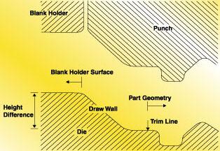 |
| Figure 2: Draw walls are used to match height differences between the blank holder surface and the product surface. |
A draw wall is a straight connection from the edge of the part to the punch opening line on the blank holder (seeFigure 1). The varying parameters are the length, angle, and radii used at both ends.
Draw walls are used to match height differences between the blank holder surface and the product surface (see Figure 2). They also are used to control the amount of metal drawn into the cavity by varying the length and the angle.
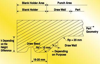 |
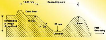
| Figure 3: Draw beads have to be located 16 to 20 mm apart from the die radius. This large radius helps to distribute the strains more equally. |
The draw wall's punch radius should be about 20 millimeters for aluminum stampings (see Figure 3). This large radius helps to distribute the strains more equally, whereas a smaller radius leads to a strain concentration near the die corner, which may cause failure. The same conditions apply to the die radius. A die radius of 10 millimeters usually is sufficient for aluminum stampings.
The minimum angle that should be used for a draw wall is 6 degrees. This angle should increase as the draw depth increases to prevent severe forming conditions. If the amount of drawing into the die cavity is not large, then a larger angle can be used to design the draw wall. If the design requires draw beads, they will be most effective if placed 16 to 20 millimeters away from the die radius (see Figure 3).
Drawbars (see Figure 4) look like exaggerated draw beads. The male bar usually is part of the punch, and the female bar is in the die. Drawbars are used to eliminate wrinkling by compensating for the excess metal caused by the differences in draw depth.
 |
| Figure 4: Drawbars look like exaggerated draw beads. The male bar usually is part of the punch, and the female bar is in the die. |
A punch radius of nine to 12 times the sheet thickness along the straight sides and a minimum radius of 12 times the sheet thickness in the corners are suggested. The die radius should be nine times the sheet thickness along the straight sides and nine to 12 times the sheet thickness in the corners. The drawbar radius should be a minimum of 20 millimeters.
A distance of 16 to 20 millimeters from the draw bead usually is sufficient for aluminum stampings. The dimensions in Figure 4are given for aluminum sheet metal with a thickness of 1 millimeter.
A basic consideration in the tryout stage is to lower the depth or increase the radius of the drawbar if tearing occurs. Wrinkling is eliminated by increasing the depth or decreasing the radius. Also, the depth of the drawbars may influence the trim line considerations.Sometimes the depth of the drawbar has to be increased to provide enough space for the trimming tool. The trimming line should not be on a radius but on a straight surface. Therefore, any addendum radius should start about 6 millimeters below the trimming line (see Figure 5).
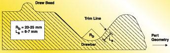 |
| Figure 5: Sometimes the depth of the drawbar has to be increased to provide enough space for the trimming tool. The trimming line should not be on a radius but on a straight surface. Therefore, any addendum radius should start about 6 mm below the trimming line. |
Taylan Altan is a professor and director of the Engineering Research Center for Net Shape Manufacturing, 339 Baker Systems, 1971 Neil Ave., Columbus, OH 43210-1271, phone 614-292-9267, fax 614-292-7219, Web site nsmwww.eng.ohio-state.edu. The ERC/NSM conducts research and development; educates students; and organizes workshops, tutorials, and conferences for the industry in stamping, tube hydroforming, forging, and machining.
T. Burk, "Addendum Design Methodology and Tool Design for Aluminum Sheet Metal Forming," Diploma Thesis, Metal Forming Institute, University of Stuttgart, Germany, 1994.

Professor Emeritus and Director - Center for Precision Forming


The Fabricator is North America's leading magazine for the metal forming and fabricating industry. The magazine delivers the news, technical articles, and case histories that enable fabricators to do their jobs more efficiently. The Fabricator has served the industry since 1970.
start your free subscription
Easily access valuable industry resources now with full access to the digital edition of The Fabricator.

Easily access valuable industry resources now with full access to the digital edition of The Welder.

Easily access valuable industry resources now with full access to the digital edition of The Tube and Pipe Journal.

Easily access valuable industry resources now with full access to the digital edition of The Fabricator en Español.
In this episode of The Fabricator Podcast, Caleb Chamberlain, co-founder and CEO of OSH Cut, discusses his company’s...


