


Contributing Writer
Object
The standards that govern equipment manufactured for use in the European Economic Area (EEA) stipulate the parameters for operator safety, including performing risk assessments and designing protective devices to minimize or eliminate hazards.
Performing a risk assessment and incorporating appropriate protection systems during a machine's design and development phase can help ensure that the machine conforms to relevant safety standards. Taking these actions before a machine is built is more efficient than adding protection systems later.
Removing or reducing operator hazards requires a three-phase approach that includes designing hazards out; guarding against hazards that cannot be designed out; and warning the operator of hazards that cannot be designed out or guarded against.
European Norm (EN) 1050 provides guidance on performing a risk assessment. Several methods are suggested, including:
For all of these methods of risk assessment, EN 1050 provides a simple mathematical formula for evaluating hazards and determining the level of risk. The formula is:
LO X FE X DPH X NP = Risk level
Where:
LO= Likelihood of occurrence, ranging from 1 (almost impossible) to 15 (certain)
FE= Frequency of exposure, ranging from 0.5 (annually) to 5 (constant)
DPH= Degree of possible harm, ranging from 0.1 (scratch or to 15 (fatality)
Object
NP= Number of persons exposed, ranging from 1 (1 or 2 people) to 12 (50 or more people)
EN-954-1 provides a qualitative form of risk assessment and, more important, describes five levels of circuit performance in the event of a component failure. These levels are identified as categories B and 1 through 4. Only category 4 fully complies with U.S. standards definitions for control reliability.
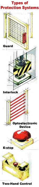
Five main categories of protection systems are guards, interlocks, electrosensitive and optoelectronic devices, emergency-stop devices, and two-hand controls.
Guards. Guards are classified into three main types—fixed, movable, and adjustable.
Fixed guards are among the simplest of protective devices. Fixed in place, they are removable only with the aid of tools. Several standards (EN 953, EN 294, EN 349, and EN 811) discuss fixed guards in detail.
Movable guards are further subdivided into Type A and Type B. Type A guards are combined with a locking device to prevent moving parts from starting up while the danger zone is accessed. Type B guards are incorporated into the control system so that moving parts cannot start up while they are within the operator's reach. Specific information is provided in EN 1088.
Adjustable guards are adjustable manually, automatically, or both, without the use of tools.
Interlocks. Two types of interlocking systems are mechanical trapped key and electrical control.
The key in a mechanical trapped key system is removable from the lock only when the hazard has been isolated. The energy source—whether electrical, pneumatic, or hydraulic—can be reduced to zero (all stored energy is dissipated) before the operator can access the hazardous area of the machine.
The principles governing mechanical trapped key interlocking systems are identified in EN 954-1, EN 1088, EN 292-1, and EN 1050.
Electrical control interlocks are useful for applications that require rapid or frequent access to a machine. They provide a safe method of entry while power to the machine is maintained. Gate control is provided by means of solenoid-controlled locks that contain safety monitoring circuits. These circuits incorporate positively guided contacts that monitor the solenoid and the physical position of the gate.
Electrosensitive and Optoelectronic Devices. Electrosensitive or optoelectronic devices provide an alternative to mechanical guarding. Although they can provide a higher level of productivity, they do have limitations—they are not suitable for every situation and they do not protect against flying materials.
Optoelectronic selection criteria include defining the zone to be guarded; defining the safety function (detecting a finger or hand, arm or body, or the presence of a person); complying with the appropriate category of safety-related control; and calculating the safety distance.
Standard prEN 999 provides the following formula for calculating the minimum distance from the danger zone:
S = (K X T) + C
Where:
S= Minimum distance in millimeters from the hazardous zone to the detection point
K= Approach speed of the body or parts of the body in millimeters per second
T= Overall stopping performance in seconds
C= Additional stopping distance in millimeters,based on intrusion toward the danger zone before actuation of the protective device
Annex C of EN 692 provides further information that specifically concerns mechanical presses. Electrosensitive and optoelectronic devices must be incorporated into the machine's control system. Therefore, every part of the control system—the relevant part of the machine's control circuit, its connection to the safety device, and the safety device itself—must be considered during the risk assessment. This is detailed in EN 954-1 and EN 61496. Further information about electrosensitive and optoelectronic devices is provided by HSG180, published by Great Britain's Health and Safety Executive.
Emergency-stop Devices. Emergency-stop devices must bring moving parts to a complete stop. For a complex machine, or a machine with parts that develop high inertia, the stop function must not damage the machine or create a dangerous situation.
Section 9 of EN 60204-1 defines three stop functions:
Category 0:Stopping by immediate removal of power to the machine actuators; all brakes or mechanical devices are actuated. This is an uncontrolled stop.
Category 1:Stopping by means of machine actuators. Power is removed after all motion stops. This is a controlled stop.
Category 2:Power remains available to machine actuators. This is a controlled stop.
Only categories 0 and 1 are used for emergency-stop or safety-stop functions.
An emergency-stop switch can take one of several forms: mushroom-headed buttons, bars, levers, kickplates, or pressure-sensitive cables. The switch must be red, and the background color must be yellow.
Two-hand Controls. Two-hand controls help to ensure that operators keep their hands away from the danger zone before initiating any movement. All types of two-hand controls must comply with the requirements of EN 292-1. Two-hand control relays must comply with EN 60204.
In the U.S., several government agencies, nonprofit organizations, and businesses—including the Occupational Safety and Health Administration (OSHA, www.osha.gov), the American National Standards Institute (ANSI, www. ansi.org), the Robotic Industries Association (RIA, www.robotics.org), and Underwriters Laboratories (UL, www.ul.com)—have developed safety standards for commercial equipment. Designing machinery to comply with accepted U.S. standards can help to establish and maintain market position.
Likewise, manufacturers that want to sell their machinery in the European Union must design their equipment to conform to the standards required in the EEA.
This article was derived from the Pilz Guide to Machinery Safety.


The Fabricator is North America's leading magazine for the metal forming and fabricating industry. The magazine delivers the news, technical articles, and case histories that enable fabricators to do their jobs more efficiently. The Fabricator has served the industry since 1970.
start your free subscription
Easily access valuable industry resources now with full access to the digital edition of The Fabricator.

Easily access valuable industry resources now with full access to the digital edition of The Welder.

Easily access valuable industry resources now with full access to the digital edition of The Tube and Pipe Journal.

Easily access valuable industry resources now with full access to the digital edition of The Fabricator en Español.
In this episode of The Fabricator Podcast, Caleb Chamberlain, co-founder and CEO of OSH Cut, discusses his company’s...


