


Contributing Writer
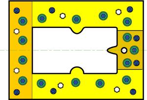 |
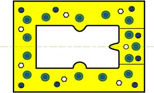
| Figure 1: Wire EDM can be used to produce a blank-through die opening such as the one illustrated here, except for the screw holes. Each of the four die sections is designed with two dowels to provide locational accuracy. |
Conventional die-sinking electrical discharge machining (EDM) was developed in the 1940s and, during the next two decades, became a well-established die-making tool. This new electrical spark die-sinking technology reduced the cost of producing die molds as well as many stamping die components. In addition, it provided a unique capability to drill and tap accurate holes in solid tungsten carbide and hardened tool steels.
Precision cutting die sections can now be cut out complete with sidewall taper or draft angles. Previously, complicated dies were made of many individual hardened sections produced by difficult surface grinder setups involving compound angles. Often, complex forms were dressed onto the grinding wheels.
The main impacts of wire EDM are reductions in the time and cost required to produce dies and in the number of die sections required to produce precision dies. Thus, die-sinking EDM has made tasks such as tapping holes in solid carbide possible while reducing the cost of die cavity and opening production. Wire EDM has simplified die construction that otherwise would require difficult surface grinding and laborious hand fitting.
It is now possible to make large die sections as single-piece details. Figure 1 shows a blank-through die opening made of four sections, each of which is large enough to provide strength and with enough screws to prevent shifting. Wire EDM has also eliminated most hand fitting that was accomplished by filing, stoning, and lapping.
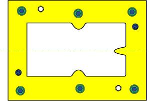 |
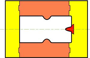
| Figure 2: Wire EDM can also be used to produce a die such as the one shown here. This one-piece construction can be less expensive to build, but repairing damage to a section of the die may be difficult. |
Wire EDM can be used to make a large one-piece blank-through die from a single piece of hardened tool steel (see Figure 2). The only machining normally completed before hardening involves producing counterbored screw and pull-out or jackscrew holes. The dowel holes can be made with the wire EDM process, although drilling starter holes can reduce machining time.
Because the cutting forces are balanced, the size of the die section must provide sufficient strength to keep lateral deflection low. This type of construction is acceptable if discarding a damaged section is more cost-effective than repairing it. Making this die detail easy to repair requires breaking the detail down into four or more sections, as shown in Figure 1.
Dowel pins are the most widely used method for positioning components in die assemblies accurately. Static friction prevents the punch and die sections from shifting. During the cutting process, both compressive and lateral forces develop. Compressive forces add to the screw clamping action that prevents shifting, while lateral forces tend to cause shifting. A sufficient number of screws should be used to provide adequate friction to prevent shifting.
The proper size and quantity of screws required can be calculated from the screw manufacturer's data. As a general rule, the clamping force of the screws must be 6.7 times the side thrust, based on a coefficient of friction of 0.15.
A misconception persists that dowels and keys prevent shifting. Because dowels and keys are elastic steel components, they deflect under load and allow some shifting. Therefore, they can only restrict or limit shifting to a minimum, provided that the loads do not result in plastic deformation. Dowels are intended to align components in a no-load condition to aid in die assembly and maintenance.
The die designer should follow torque-versus-tension graphs for screws used in die designs. Many screw manufacturers provide data for this purpose. Because of the wide variety of threaded fasteners that are used in die making and die setting, an individual manufacturer's data should be followed regarding tensile strength, fatigue strength, and tightening requirements.
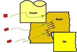 | 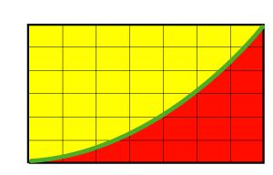 |
| Figure 3: Cutting forces tend to cause tipping, bending, and shifting of die steels. | >Figure 4: This graph illustrates how lateral shifting force increases exponentially as a function of cutting die clearance. |
Both punch and die steels for cutting must be designed to allow for clearance increases caused by deflection (see Figures 3 and 4). Clearance increases can be caused by the effects of any or all of the following on trimming or cutting steel:
Properly placed and tightened screws of suitable sizes can prevent a die steel from tipping or revolving about its back lower edge.Two important rules apply to screw placement. First, screws should be placed as near as is practical to the working edge of a section, consistent with strong cutting edges. Because these screws have a greater moment arm, they are better suited for restricting tipping.
Second, tipping is not as likely to occur if the height-to-width ratio of the steel is less than or equal to one. In such cases, the vertical forces tend to counteract side thrusts without the aid of screws. Tipping occurs more often in form dies, where side thrusts exceed vertical forces.
Die block thicknesses are governed by the strength required to resist the cutting forces and the amount of material to be removed through sharpening the tool during the service life of the section. Another factor is the type and thickness of the material being cut.
 |
| Figure 5: This drawing shows a one-piece blank-through die opening that has additional screw, dowel, and jackscrew holes. The section can be cut apart with wire EDM to repair sections of the die or to facilitate welded repairs. |
For very thin materials, 0.5-inch (12.7-millimeter) thickness may be sufficient. However, finished thicknesses are seldom less than 0.875 inch (22.22 millimeters), which provides enough material for blind screw holes and resharpening. The one-piece die block illustrated in Figure 5 has extra screw and dowel holes to permit cutting the tooling into several sections to facilitate repair. Each section has enough screws and dowels to provide proper location and prevent shifting.
For heavy work, keys may be needed to prevent die section shifting. Relying on screw tension alone may not be economical because the required screw sizes would be very large. This is especially true for flanging dies because the wedge action can create side thrusts greater than the vertical forces.
The modulus of elasticity under a shear stress, sometimes called the shear modulus of rigidity, can be used to address this problem. For plain carbon or alloy steel in either the soft or hardened state, this modulus is about 12 million pounds per square inch (PSI) (83 gigapascal). A detailed mathematical procedure for determining key requirements is available in standard engineering handbooks.
 |
| Figure 6: This drawing illustrates how a blank-through die opening can be designed with interlocking section. Although not shown in this drawing, screws and dowels can be used to hold the five-section design to the shoe. |
Keys are used most frequently in die construction to prevent lateral shifting. They are placed in milled pockets in the die shoe and contact die sections that are subject to shifting. A key may be a separate detail or an integral part of the section.
Another application in which keys can be used to prevent shifting is shown in Figure 6. Four key projections are designed into the top and bottom sections, and they mate with pockets in the end sections. The projecting small section is dovetailed into a larger section. This feature makes the section easy to replace if excessive wear or breakage occurs. Another advantage is that the section can be made of the most appropriate tool steel for the application.
For example, D2 or M4 tool steels wear well in most applications but may be subject to chipping. S7 could be used to reduce chipping, although it wears more rapidly than does D2 or M4. The small detail can be replaced as needed during periodic die maintenance.
EDM is an essential machining process upon which most modern die construction depends. Properly applied during the die design process, EDM can be used to build dies that are low in cost and easy to repair. EDM construction offers trade-offs between initial die cost, service life, and ease of repairability. The die specifier and designer should consider the desired die life and severity of the operation and design the die accordingly.


The Fabricator is North America's leading magazine for the metal forming and fabricating industry. The magazine delivers the news, technical articles, and case histories that enable fabricators to do their jobs more efficiently. The Fabricator has served the industry since 1970.
start your free subscription
Easily access valuable industry resources now with full access to the digital edition of The Fabricator.

Easily access valuable industry resources now with full access to the digital edition of The Welder.

Easily access valuable industry resources now with full access to the digital edition of The Tube and Pipe Journal.

Easily access valuable industry resources now with full access to the digital edition of The Fabricator en Español.
In this episode of The Fabricator Podcast, Caleb Chamberlain, co-founder and CEO of OSH Cut, discusses his company’s...


