


Contributing Writer
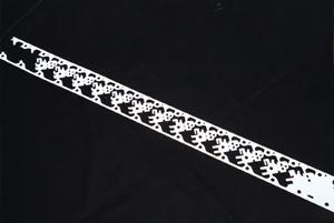 |
| Figure 1: This part was rotated in the strip to increase the consistency in critical tolerances. |
The decision to produce a part progressively is usually determined by two factors: the volume of production and the complexity of the part. These two factors are instrumental in the design and construction of the tooling. It is important to address all factors that will contribute to the desired level of part quality, tool maintenance, and tooling life. Trade-offs will be necessary to reach most decisions, and all will affect tooling costs.
The process begins with determining how the part will be run through the die. This is governed by the features of the part and the locations of the datums and critical tolerances. Then, the trade-offs begin.
Optimizing material usage may require rotating the part in the strip, which changes the grain direction of the steel in the part and thus can affect the strength of any forms in the part. Forming with the grain can cause cracking and fatiguing of the metal and make holding consistent form angles more difficult. Therefore, the form will be far more susceptible to problems associated with the chemical makeup of each coil that is run.
For example, Figure 1 shows a part for the computer industry that was rotated in the strip to guard against inconsistent form angles that could be caused by differences between coils. The part contained critical dimensions with 0.025-millimeter tolerances dependent on the forms. Rotating the strip to ensure more consistent forms was not the most efficient use of material. In this case, however, part tolerances won out over optimizing material usage.
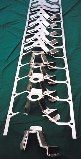 |
| Figure 2: Compromises among excessive lift, material use, and tooling cost and complexity were necessary to form this part. |
Part configuration could provide a second motivation for rotating a part in the strip. If cam forming or piercing is required to make the part progressively, rotating the part may be the best, and sometimes only, option because the cam and driver can take up a significant amount of room. The part typically is rotated so that the cams' functions are perpendicular to the coil. This provides the easiest and most accessible condition for the cams.
Often, a compromise between rotating a part to optimize material usage and angling the cams to keep them outside of the coil is the final result. This could increase piece part and tooling costs. To produce the part progressively, however, such a compromise may be necessary.
A third consideration that may require rotating the part in the strip is the amount of lift that is needed to carry the strip through the die. Lift can sometimes be reduced significantly or eliminated by properly rotating a part.
If all forms in a part are in the same direction, lift can be eliminated by forming upward. This usually adds to the cost of the die. When the part has forms in opposite directions, compromises must be made among excessive lift, poor material use, and the complexity and cost of the tooling.
One such compromise is shown in Figure 2. The part is carried through with a ladder-style carrier, which adds material to the coil width because only two small areas are available for carrying the part. Also, because of the shape and length of the forms, a significant amount of lift is needed. External stock lifters carrying the ladder strip work well in high-lift situations.
One final consideration for part orientation within the strip is that a part should be rotated so that the feed is as short as possible. This is especially true for heavier materials and narrow coils. The slitting process can cause camber in coils that can make feeding difficult. A shorter progression feed runs faster and has less chance to cause feed problems. When a substantial difference between the length and width of the part exists, it is usually more cost-effective to build the tooling with the shorter lead.
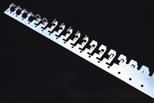 |
| Figure 3: One side of the strip is used to carry this part through a progressive die. |
How parts are carried in the strip affects how well the die feeds, the ability to lift the strip for feeding, and the ability to produce consistent-quality parts.
Three basic options are available for carrying a part, although many variations of each also can be used. In the most straightforward approach, parts are carried by the scrap between them. Excess material equal to one to two material thicknesses per side is required for trimming. This method typically produces minimal scrap.
Certain part configurations are needed to use this method. When rotated and laid out end to end, the parts must have enough usable area on both the leading and trailing edges of the progression (see Figure 3).
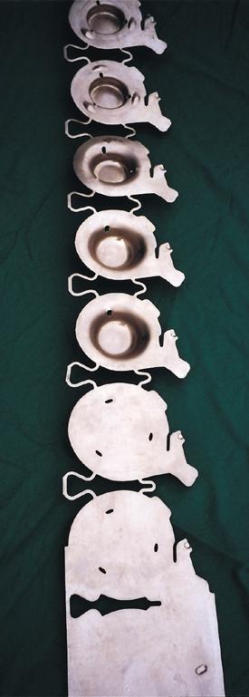 |
| Figure 4: The parts shown here are carried by the scrap between them, which also serves as stretch webs for the center draw. |
The second basic strip option, in which a part is carried on one side of the strip, is shown in Figure 4. This style is suitable for parts that require a great deal of forming on as many as three sides. It also improves accessibility if cam piercing or forming is required.
Lifting the strip through the die can become more difficult when this carrier option is used. A stock lifter on the edge of the strip is not sufficient—lifters are needed in the center of the strip for balancing, or feeding the strip through the die can become a problem. If large or numerous flanges are to be formed down, achieving the proper lift can be difficult.
This type of carrier can cause another feeding problem. Trimming a large quantity of material from one side of the coil can cause camber in the strip as stresses are released from the steel. The more progressions in a die, the greater is the risk of feed and pilot alignment problems caused by camber.
Part configuration, stock material thickness, and how narrow the carrier must be are all factors that influence whether camber becomes a problem. To prevent camber, the coil width should be increased so that the carrier side of the coil also can be trimmed. The additional trim releases stresses from the opposite side of the coil and balances the strip. Even with the additional trim, carrying the part on one side of the strip can be the most effective method to run a part from a material usage standpoint.
The third carrier option is the ladder style. Some of the advantages of the ladder carrier were discussed earlier. These carriers work well with complex parts and with those requiring significant amounts of lift. Because this method allows a strip to feed easily, it also is often used in applications in which higher feed rates are needed.
The ladder carrier uses more material per part. Often, however, a part cannot be produced progressively any other way. If production volumes are borderline to begin with in terms of justifying progressive tooling, the added costs of the more complex progressive die and additional material waste may make producing the part through multiple operations a better option.
PilotingDecisions on part rotation and carrier type must be made concurrently with a third consideration, piloting. The type, locations, and number of pilots all affect the progression, coil, and carrier type.
Choosing pilots begins with examining the part configuration and tolerance requirements. Is piloting off of holes within the part possible or even acceptable? If a part contains holes, they must be large enough if they are to be used as pilots. Holes should be spaced as far apart as possible to help increase accuracy, and they must be in the proper locations if they are used to stabilize a strip and help with the forming taking place in the die.
The tolerances of the proposed pilot holes in the part should be considered. If the hole diameter tolerance is very tight, even slight elongations caused during forming may produce scrap parts. Elongation could be caused by something as simple as an old feeder or one that is slightly out of adjustment. If a pilot is located in the scrap or the carrier, slight elongation is acceptable, as long as the piece part dimensions remain within tolerance.
At times, two different sets of pilots may be required. In these applications, both sets of pilots should be pierced at the same time to provide an accurate transition from the first set of pilots to the second. When a significant amount of stripper travel is involved, problems can occur. The pilots will contact the material as they line up the strip. If considerable stripper travel is involved, the pilots will rub on the pilot hole for the complete distance, which can cause a burr on the hole and lead to galling of the pilots. The best solution is to guide the stripper and place the pilots in the stripper.
Determining how a part exits from a die is often overlooked until the end of the design. It is at times, however, the pivotal factor in determining how a die is designed. Removing the part from the die may require rotating the part, using a different type of carrier, or changing the sequence of operations within the die.
The locations of the forms in the part and their relationship to where the part is carried directly bear on how or whether the part comes out of the die. A ladder strip provides the easiest method for removing a part from the die. Usually, a part can be cut and blanked through the die.
When a die is designed so that parts are cut and allowed to fall off the end, several factors must be considered. For instance, the part weight must be sufficiently off-balance to allow it to fall off the die block. A shedder pin can be added to the top stripper to ensure that the part exits the die.
If form tabs or flanges are formed down on the part, clearances must be added. If that is not possible, it may be necessary to redesign the die to ensure that the part exits. If flanges are formed up, the advancement of the strip sometimes will kick the part out of the die.
Once the basic design is determined, the exact number of stations needed can be assessed. It is important to keep die construction in mind when finalizing strip layout. Often, empty stations should be included to prevent weakening a die if further modifications become necessary. In addition, the ease of maintaining the tool should be kept in mind.
As the complexity of a tool increases, the degree of confidence in the design also plays a role in deciding how many stations should be included. If questions arise as to whether the part will draw properly or the form will come out as desired, one or more empty stations should be added—the more uncertainties, the higher the number of empties that should be added.
If a die is built without empty stations and additional operations must be added later, options are few. In almost all such cases, the integrity of the die must be compromised to accommodate the modification. Oftentimes, very undesirable maintenance conditions must be built into the die. Either situation could result in producing a die that breaks repeatedly and is costly to maintain.
Getting the fundamentals right is the key to producing a quality, cost-effective die and piece part. The more complex the die, the more important are the decisions on the fundamentals. With proper evaluation and the proper compromises, the best option can be determined. This will give a strong, good-feeding die that is easily maintainable. The die will produce consistent, quality parts to print. The proper decision should provide the best value for a company's tooling dollars.


The Fabricator is North America's leading magazine for the metal forming and fabricating industry. The magazine delivers the news, technical articles, and case histories that enable fabricators to do their jobs more efficiently. The Fabricator has served the industry since 1970.
start your free subscription
Easily access valuable industry resources now with full access to the digital edition of The Fabricator.

Easily access valuable industry resources now with full access to the digital edition of The Welder.

Easily access valuable industry resources now with full access to the digital edition of The Tube and Pipe Journal.

Easily access valuable industry resources now with full access to the digital edition of The Fabricator en Español.
In this episode of The Fabricator Podcast, Caleb Chamberlain, co-founder and CEO of OSH Cut, discusses his company’s...


