


Contributing Writer

The drawing pad, otherwise known as the binder, blank holder, or pressure ring, is one of the most important components of a drawing and stretching operation. Its shape, thickness, deflection, and surface quality are critical features. In addition, the material it’s made from is crucial.
A draw pad is a pressure-loaded ring, either flat or contoured, that surrounds the male forming or drawing punch. It controls metal flow into the draw die cavity and over the drawing punch. Draw pads can get their needed force from a variety of pressure systems, including gas or nitrogen springs, a press cushion system, urethane or coil springs, and hydraulic cylinders.
Draw pads usually are made from a hardened, wear-resistant tool steel, solid carbide, or a type of hardenable cast iron.
Despite common misconceptions, the true function of a draw pad is to keep the metal from wrinkling during the drawing process. However, if the product can be produced only by stretching the metal, the draw pad can be used to prevent the material from flowing inward. In this case, it commonly is referred to as a binder, because it binds or squeezes the material so that it cannot flow inward.
Too many stampers and die shops attempt to control how much metal feeds inward by altering the amount of pressure being applied to the sheet metal. As more pressure is applied to the sheet, inward flow and pressures decrease, which results in more feeding. Although changing the holding pressures can alter the amount of material flow, it can be very difficult to get consistent amounts of stretch and flow. For this reason, flow should be controlled through the use of draw beads and the blank size and shape.
Draw pads come in many different shapes, sizes, and thicknesses, depending on the part shape. Parts with a lot of contours and curvature typically require a pad that is curved with respect to the part shape. However, for square, rectangular, or round shell parts with flat bottoms, flat pads usually are used (see Figure 1).
The shape that the sheet metal takes when being formed to the draw pad often is referred to as the “wrap.” The wrap is crucial to the success of the drawing operation. If the wrap is undevelopable, it means the draw pad will be shaped to force some metal to push up into the draw pad (punch) opening before forming punch contact. This is desired when stretch-drawing parts that contain a lot of shape that must be obtained through stretching or embossing features in the center area of a part.
For example, inner automobile doors often use an undevelopable wrap. The inner door usually is not defined as a Class A or exposed surface, so minor defects caused by the metal being creased before punch contact are permissible. Using an undevelopable wrap to stretch-draw a Class A part often results in surface defects that are pre-established during draw pad contact—and they are nearly impossible to get rid of (see Figure 2).
If a wrap is developed, it means the blank will not buckle, twist, or crease when taking the shape of the draw pad. This wrap type is desirable when stretch-drawing items such as exposed Class A body panels, such as outer doors or fenders. Draw pads often are shaped to maximize punch contact and unify the depth of drawing that is taking place. If the part has a contoured flange, the drawing pad likely needs to be contoured to a similar curved profile. Having a curved drawing pad can reduce the severity of forming. In addition, using a contoured drawing pad can result in less material usage.
Even minor deflection in a drawing pad can result in a loss of flow control. For this reason, drawing pads should be thick enough and made from a hardened material that resists deflection.
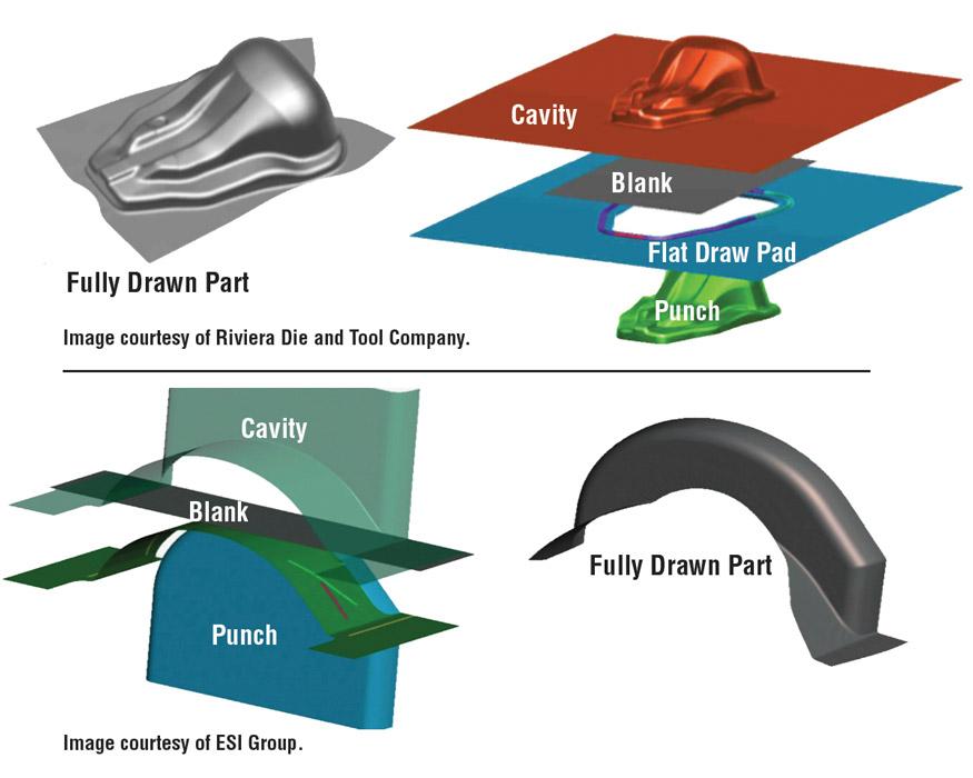
Figure 1
Parts with a lot of contours and curvature typically require a draw pad that is curved
with respect to the part shape. However, for square, rectangular, or round shell parts
with flat bottoms, flat pads usually are used.
While no simple formula exists to determine draw pad thickness, finite element analysis (FEA) can be used to determine the amount of deflection. A good rule of thumb: Thicker is better. Even if the draw pad is thick enough to minimize deflection, the press bolster and ram will deflect.
The correct pad thickness is a choice based on the following three factors:
1. The amount of draw pad deflection that will happen during the drawing process. Deflection occurs regardless of pad thickness, but a thicker draw pad will deflect less than a thinner pad. Deflection as little as 0.001 in. on thin metal often results in wrinkling between the draw pad and die face. Severe deflection will result in a loss of metal flow control. Using equalizers can help minimize this effect.
2. The allowable thickness (shut height) of the die. When engineering a die, the designer must consider the overall thickness of the die, as well as the press ram travel. The press shut height and press stroke limits often determine the maximum thickness the draw pad can be while still allowing the die to be placed in the specified press.
3. Die cost. Tool steel costs money. Thicker pads result in an increase in die cost. Although numerous factors affect drawing operations, the geometry of the drawing pad is critical. Take a good look at the advantages and disadvantages of using a contoured drawing pad, and use data to make your decision.
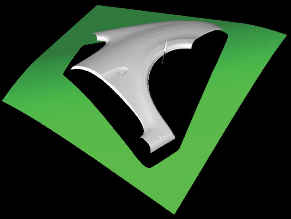
Figure 2
Using an undevelopable wrap to stretch-draw a Class A part often results in surface
defects that are pre-established during draw pad contact —and they are nearly
impossible to get rid of. Image courtesy of ESI Group.


The Fabricator is North America's leading magazine for the metal forming and fabricating industry. The magazine delivers the news, technical articles, and case histories that enable fabricators to do their jobs more efficiently. The Fabricator has served the industry since 1970.
start your free subscription
Easily access valuable industry resources now with full access to the digital edition of The Fabricator.

Easily access valuable industry resources now with full access to the digital edition of The Welder.

Easily access valuable industry resources now with full access to the digital edition of The Tube and Pipe Journal.

Easily access valuable industry resources now with full access to the digital edition of The Fabricator en Español.
In this episode of The Fabricator Podcast, Caleb Chamberlain, co-founder and CEO of OSH Cut, discusses his company’s...


