


Contributing Writer

Choosing the proper guidance and heeling method is critical to the success of any stamping operation. Improperly guided and heeled die shoes may result in cutting and forming sections interfacing with the wrong clearances, severe deflection, and die damage.
Guide pins, sometimes referred to as guide posts or pillars, are cylinder-shaped, hardened tool steel, preci-sion-ground pins that fit into precision-ground sleeves called bushings to align the upper and lower die shoes precisely. Both the guide pins and the bushings are ground to within 0.0001 in.
Two basic styles of pins are avail-able: friction pins (also referred to as plain bearing pins) and ball bearing pins (see Figure 1).
Friction pins typically are about 0.0005 in. smaller in diameter than the inside diameter of the guide bushing. Friction pins and bushings usually cost less than ball bearing-style pins and are used when a great deal of side thrust is expected in the die. Because they generate a lot of friction, these pins typically are not desirable for high-speed stamping operations.
To minimize the friction, the bushings often are lined with a special wear-resistant material called aluminum bronze. The aluminum bronze may contain graphite plugs that help reduce friction and wear. Friction pins often are lubricated with high-pressure grease as well to reduce friction.
One drawback of friction pins is that they can complicate the process of separating the die, especially with larger dies. The upper and lower die shoes must remain parallel during the separation process, as cocking the die may result in bending a guide pin. Many toolmakers use heavy-duty pry bars to help separate the die.
Depending on the application, friction pins and bushings can be press-fit into the die shoes or installed using special clamps that secure them to the die shoes. These types are referred to as demountable guide pins and bushings.
Ball bearing pins are the most commonly used guide pins. They ride on a series of ball bearings contained in a special aluminum ball cage that permits the bearings to rotate without falling out.
Since the pins don’t create much friction, they are suitable for high-speed operations. They simplify the separation of the upper and lower die shoes and, because they use ball bearings, these guide pins can be manufactured with great accuracy.
The diameter of the pin and two ball bearings is 0.0002 in. larger than the inside diameter of the bushing. This type of fit, called negative slope, is the reason that ball bearing pins are referred to as ultraprecision guide pins.
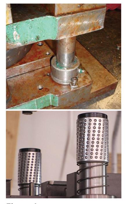
Figure 1
The two main styles of guide pins are
friction pins (top) and ball bearing pins
(bottom).
Ball bearing guide pins mounted on the bottom die shoe must be spring-loaded so that the cage enters the bushing before the guide pin. In an ideal situation, when the die is in the press, the ball cage never fully exits the bushing. This isn’t always possible, though, as most stampers have a limited number of presses with fixed stroke lengths. Like friction pins, ball bearing guide pins can be purchased or manufactured as press-fit or demountable.
Large drawing dies don’t always use guide pins and bushings. Instead, guide blocks and heel/thrust blocks are used (see Figure 2).
Guide blocks are special steel blocks that are precision-machined, screwed, doweled, and welded onto both the upper and lower die shoes. They contain hardened tool steel components called wear plates. Guide blocks are used to align and heel dies that do not require ultraprecise alignment.
Heel blocks can be used to heel the die in any or all directions. Box heels often are used to guide and heel the die in all directions, meaning that four surfaces are used to heel the die. While a die needing heeling might contain two or more heel blocks, not all die shoes contain heels, especially dies with well-balanced forces about the centerline of the tool.
When the forces in a die are unbalanced, heel blocks may be used in addition to guide pins. For example, when only one side of the part is being cut or bent, the side forces are unbalanced, which can result in the die shoes deflecting in opposite directions. In another example, the forces occurring during strip starting in a progressive die might not be balanced until the die is fully loaded.
Wear plate selection for heel blocks is critical. In most cases, the heel block on one shoe has a steel wear plate, while the heel block on the opposite shoe has a wear plate made from aluminum bronze or another dissimilar metal. If the two opposing plates are made of the same metal, the result can be high friction, heat, and galling or cold welding of the wear plates. However, they do often contain graphite plugs that help to reduce friction.
Regardless of the type of guide pins and heels used, they are not intended to compensate for a poorly maintained or sloppy ram in a press. The press ram must be guided and heeled precisely to resist tipping or moving side to side.
Avoid using too many or oversized guide pins to correct the ram. Guide pins are intended solely to align the upper and lower die shoes and the components and sections mounted to them.
A good guidance system is highly important. Proper alignment of each die component is critical to the success of the die. A poorly guided die is a recipe for downtime, poor product quality, and severe die damage.
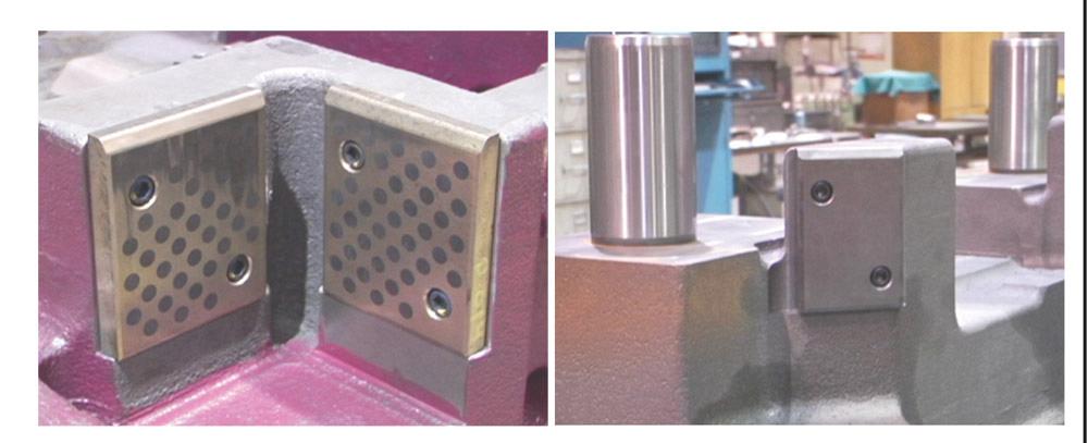
Figure 1
Guide blocks (left) and heel/thrust blocks (right) are used in large drawing dies
instead of guide pins and bushings.


The Fabricator is North America's leading magazine for the metal forming and fabricating industry. The magazine delivers the news, technical articles, and case histories that enable fabricators to do their jobs more efficiently. The Fabricator has served the industry since 1970.
start your free subscription
Easily access valuable industry resources now with full access to the digital edition of The Fabricator.

Easily access valuable industry resources now with full access to the digital edition of The Welder.

Easily access valuable industry resources now with full access to the digital edition of The Tube and Pipe Journal.

Easily access valuable industry resources now with full access to the digital edition of The Fabricator en Español.
In this episode of The Fabricator Podcast, Caleb Chamberlain, co-founder and CEO of OSH Cut, discusses his company’s...


