


Contributing Writer

All too often designers employ open wall angles simply because they’ve been told that they are easier to form than vertical walls. Although this statement may be true for many part geometries, it is certainly not true for all. Sometimes a draft angle can be desirable; other times it can be problematic.
To decide if the walls of a feature or part should be perpendicular or angled, you need to consider several factors.
Thin metals are far more susceptible to wrinkling and splitting than thicker metals of the same type. In addition, keep in mind that thin metal will not stretch as far as thick metals. Be sure to consider the metal’s stretch distribution characteristics as well.
The location of the part feature or wall of the part in reference to the blank edge is known commonly as the limiting draw ratio. And the limiting draw ratio determines whether the feature is to be stretched or drawn.
In other words, you need to decide whether a great deal of metal will be flowing inward to feed the feature (drawing), or if the feature will be created through the process of stretching.
When drawing a round cup, you are transforming a larger-diameter blank into a smaller-diameter cup. For this to take place, the metal must do two things:
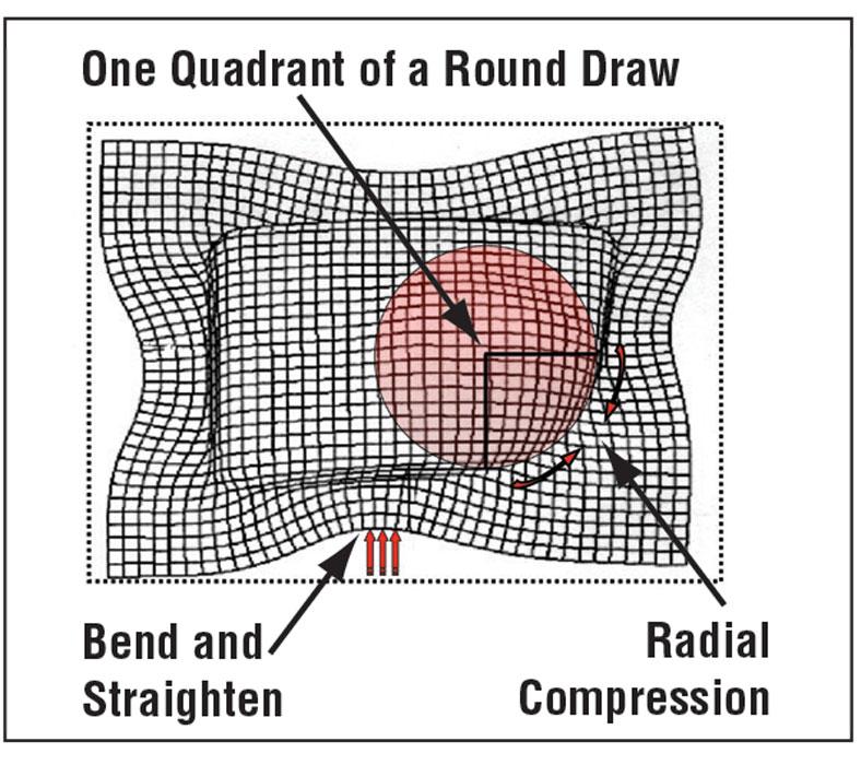
Circumferential compression also occurs in the corners of a square or rectangular drawn shell or box. In a square drawn shell, the corners basically are one quadrant or one-quarter of a round draw. This geometry forces the metal in the corners into radial compression. The sidewalls of the drawn box are in bend and straighten deformation (see Figure 2).
Because there is little or no compression during this deformation mode, the metal flows inward with very little resistance. This difference in resistance causes the blank to deform in an odd shape, resulting in “ears” on the drawn part.
Very simply, metal in compression has a resistance to flow, and metal not in compression has very little resistance to flow. If the compression that occurs during the flow of the metal is controlled, the metal will remain flat and most likely increase in thickness. However, if the metal is not in control, it most likely will wrinkle.
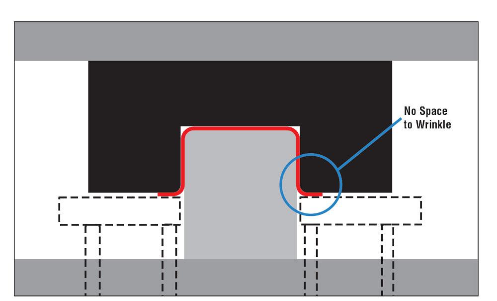
During the drawing process of a vertical wall, the metal either is trapped between the die face and drawing pad or between the walls of the drawing punch and cavity, so there is not enough space to allow the metal to wrinkle (see Figure 3).
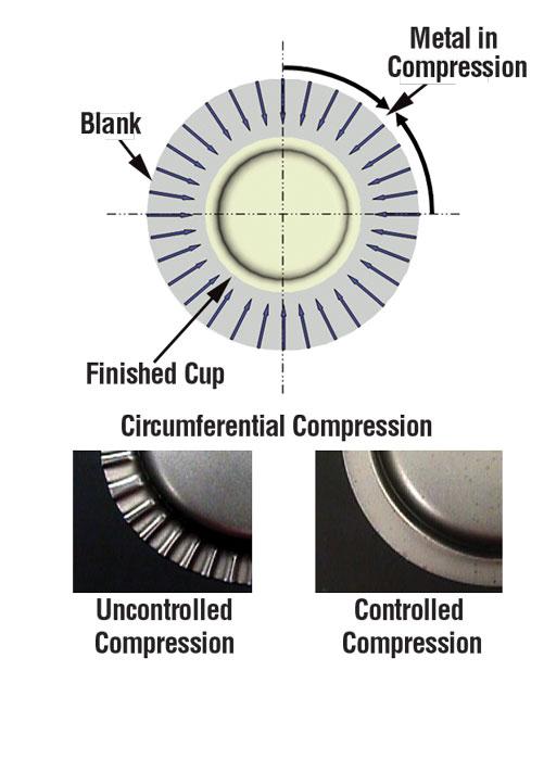
Figure 1
In round cup drawing, the outside diameter
must squeeze together to create the
smaller cup circumference. This process
is called circumferential compression.
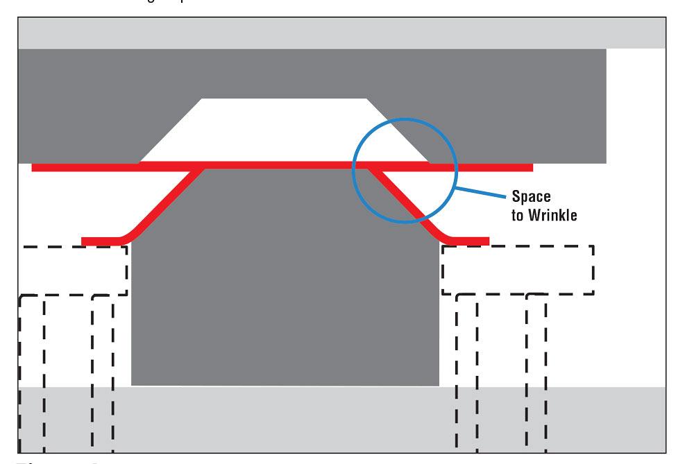
However, if the wall is angled, the drawing pad must be placed outside the entire drawing punch to travel downward a sufficient distance and achieve the desired depth of the part or feature. This leaves a great deal of metal out of control and free to wrinkle in compression (see Figure 4). This uncontrolled radial compression will occur only in the radial profiled areas of the part that force the metal into compression.
Any feeding inward of the material from the drawing pad will only magnify the amount of wrinkling. However, if the metal is prohibited from feeding inward, the part might split. In certain cases, both severe wrinkling and splitting can occur. In those cases, you should design the wall as vertical.
The following guidelines can help you to make a good, data-based decision about which wall angle to use.
Open wall angles are desirable if the following conditions exist:
Vertical walls are desirable if the following conditions exist:
One of the most difficult part shapes to draw is a cone, and the culprits are open wall angles and pure compression. Don’t assume that putting a large draft angle on a punch will automatically improve the formability of any part.


The Fabricator is North America's leading magazine for the metal forming and fabricating industry. The magazine delivers the news, technical articles, and case histories that enable fabricators to do their jobs more efficiently. The Fabricator has served the industry since 1970.
start your free subscription
Easily access valuable industry resources now with full access to the digital edition of The Fabricator.

Easily access valuable industry resources now with full access to the digital edition of The Welder.

Easily access valuable industry resources now with full access to the digital edition of The Tube and Pipe Journal.

Easily access valuable industry resources now with full access to the digital edition of The Fabricator en Español.
In this episode of The Fabricator Podcast, Caleb Chamberlain, co-founder and CEO of OSH Cut, discusses his company’s...


