


Professor Emeritus and Director - Center for Precision Forming
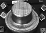
Figure 1A commercially available optical measuring system can be used to obtain data on the deformation of a stamped component.
Variations in incoming sheet material quality, tool temperatures, press and tool deflection, and lubricant performance result in deviations in formed part quality. Part failures interrupt production and can cause tool damage; thus, in addition to the initial tryout period, adjustments are routinely made during production to maintain good formed part quality.
Real-time or online monitoring of the stamping process has become essential to improve stamped part quality and prevent interruptions in production. Many types of sensors are used in production to monitor such process conditions as press tonnage, press slide movement, tool condition, tool alignment, lubricant quantity, and sheet material flow.1
Optical measuring technologies have found increased application in the sheet metal forming industry. Figure 1 shows a commercially available optical system used to obtain the deformation of a stamped component.
Before deformation, the sheet is marked with a grid of dots, using chemical etching, laser marking, or other marking techniques. For measurement purposes, one or two scale bars and some coded markers are placed directly on the part or near it. A high-resolution digital camera then is used to take shots from different viewing directions.
After images are taken, the optical system defines in each image the exact centerpoint of all marked dots. Then the images are virtually assembled with photogrammetric techniques to represent the object as a virtual 3-D model. From this virtual assembly, the center of each marked dot on the object is defined in true 3-D coordinates.
The calculated 3-D points define the exact form of the stamped sheet part. The deformation (stresses and strains) introduced by the stamping process can be calculated easily from the local distortion of the regular grid pattern on the sheet surface.2
In stamping, the main applications of optical technology are:
Depending on the application, specialized commercial software is available to process the digital images. The use of this technology also can verify and optimize numerical simulation programs for forming processes. These measuring technologies are being used increasingly for automated inspection tasks by integration of automatic vision systems into the process. For example, these cameras can be located at the exit of the stamping press to take real-time pictures of the deformed part.
Figure 2 shows an example of real-time monitoring of material flow in a deep-drawing process through the use of position sensors. The flange insertion position sensor (left) consists of a thin metal tongue that touches the outer edge of the blank sheet at the gap between the die and blank holder during the entire process.
This sensor, and others that have different designs but similar functions, detects the movement of the flange during deep drawing. Measured flange movement or draw-in versus the drawing depth can indicate the part quality. Any deviation from a prescribed tolerance range can be used to describe the potential failure.
Figure 2Real-time monitoring of material flow in a deep-drawing process can be done using position sensors. The flange insertion position sensor (left) consists of a thin metal tongue that touches the outer edge of the blank sheet at the gap between the die and blank holder during the entire process.
The right side of Figure 2 shows a similar concept used for real-time monitoring of wrinkles in a deep-drawing process. Two position sensors are installed, one in the die and one in the blank holder. When a wrinkle occurs, the gap between the die and blank holder increases. Thus, the two sensors can detect and record the height of the wrinkle.
With real-time monitoring of the wrinkle height and flange movement, the blank holder force can be increased or decreased through a closed-loop control system.3 Using this principle, researchers at the University of Hanover, Germany, designed and built a closed-loop control system for deep drawing of rectangular pans using a multipoint cushion system. Contact-free optical sensors were placed at multiple locations around the flange periphery to detect material flow (wrinkles and flange movement). The developed closed-loop system was tested by varying the initial blank shape, and it gave good results.4
This column was prepared by Ajay D. Yadav, graduate research associate, of the Center for Precision Forming (CPF), The Ohio State University, for Taylan Altan, professor and director of the CPF, 339 Baker Systems, 1971 Neil Ave., Columbus, OH 43210-1271, 614-292-9267, www.cpforming.org. The CPF conducts research and development; educates students; and organizes workshops, tutorials, and conferences for the industry in stamping, tube hydroforming, forging, and machining.

Professor Emeritus and Director - Center for Precision Forming


The Fabricator is North America's leading magazine for the metal forming and fabricating industry. The magazine delivers the news, technical articles, and case histories that enable fabricators to do their jobs more efficiently. The Fabricator has served the industry since 1970.
start your free subscription
Easily access valuable industry resources now with full access to the digital edition of The Fabricator.

Easily access valuable industry resources now with full access to the digital edition of The Welder.

Easily access valuable industry resources now with full access to the digital edition of The Tube and Pipe Journal.

Easily access valuable industry resources now with full access to the digital edition of The Fabricator en Español.
In this episode of The Fabricator Podcast, Caleb Chamberlain, co-founder and CEO of OSH Cut, discusses his company’s...


