


President
Editor's Note: This is the second in a series of seven articles that identify and define the need for a new theory on the net shape processes (of which draw forming is one) and that explain the general content and configuration that new theory must have.
Metrics is how things are measured. While units of measure (size) are standard, there is an implicit conceptual meaning to them as well. The linear measures (inches, millimeters, yards, and meters) measure the straight-line distance between two points. Bars, pounds per square inch, and pascals are standard units for measuring pressure, or stress, which has a totally different conceptual meaning.
For draw forming, the customer generally views the value of the stamping in quantifiable terms such as:
All of these conditions can be measured and quantified, and the measured values can be compared with the customer's expectations and evaluated for acceptability. If a part is not acceptable, the process must be changed to alter the measured condition so it will be acceptable.
For instance, if a part is coming out of the press too small or too large, the die can be changed to correct the error. The die is made to the size and shape of the part to be made.
Part thickness and strength are the result of the material's properties, as well as the strain induced by the die. Splits, wrinkles, and variations in size or shape do not exist in the die, but are caused by forces imposed on the material as it is being formed.
The question becomes, what processing variables must be changed, and how must they be changed to correct the condition of the formed part?
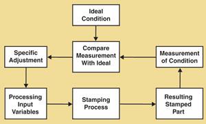 |
| Figure 1 The classical feedback control loop measures a process output by comparing the measurement with ideal conditions and makes adjustments to inputs to alter the process's performance. |
The processing variables fall into three categories: die features, press line adjustments, and material.
Die Features. The features of the die that can be adjusted to cause a particular condition to form on the part are:
These die features are variables only until the die is built or modified. Once built into the die, these features cannot be changed except by stopping production and physically modifying the die.
However, the condition of each of these can be measured. Nearly all are shapes that can be measured with linear or angular units such as millimeters of length or degrees of angle. Some, like binder force (if built into the die as a nitrogen manifold system), can be measured with pressure units of pounds force (or MN) or can be represented by the nitrogen pressure in PSI units or kilopascals (kPa).
Press Line Adjustments. Processing variables that can be adjusted during the production run include:
The condition of each of these variables can be measured.
Material. The condition of the incoming material also can be measured and changed. The controllable conditions of the incoming material are:
Ideally, when a condition of the stamped part does not meet the requirements, a processing variable is adjusted to make it conform.Figure 1shows the classic feedback control loop.
The problem with draw forming is that the control relationship is not directly quantifiable. For example, if a part has a wrinkle, which process variables must be changed, and how much should they be changed? Often the measurement units (metrics) are different, and the conceptual meaning always is different between the product condition and the processing input variable.
There is no "wrinkle control" variable/adjustment in the system. The same controllable input variables that influence the creation of wrinkles also influence splitting, springback, thinning, and yield strength.
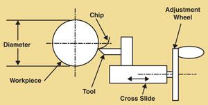 |
| Figure 2 In the simple non-net shape process of turning a shaft in a lathe, the output diameter condition of the process is measured by the linear metric of millimeters. |
The relationships between the processing input variables and the output conditions of the stamping often can be discovered through a designed experiment. Such experiments are usually very time-consuming and expensive, and the results of one experiment cannot be directly and quantitatively applied to any other part, die, material, or press.
Net shape processes, like draw forming, are fundamentally different from the non-net shape processes, so they must have their own processing theory.
For example, in the simple non-net shape process of turning a shaft in a lathe (see Figure 2), the output diameter condition of the process is measured by the linear metric of millimeters. The conceptual meaning of the measurement is the shaft diameter. The product specification for the shaft diameter is some number of millimeters, and the specification (ideal) has the same metric and conceptual meaning as the measurement. The measurement and the specification can be compared directly and any differences expressed as an error.
The processing input variable is the position of the cross slide of the lathe, controlled directly by the adjustment wheel, which has a calibration scale in millimeters. The calibration scale on the adjustment wheel has the same metric (millimeters) and the same conceptual meaning (diameter of the workpiece) as both the specification (ideal) and the measurement. The cross-head adjustment has no influence on any other condition of the workpiece.
This unity of metrics is in stark contrast to the disunity in draw forming, typical of the net shape processes.
The problem with the product requirements and the process input variables having different metrics and different conceptual meanings is just one of several differences that make the net shape processes seem to defy direct engineering. The result has been a regression to an art-/experience-based approach to engineering the dies and processes.
Even though draw forming processes now are routinely checked with finite element computer simulations, these simulations check only the experience-based designs. The simulation does not design anything. The results of the simulation, like a physical tryout of the actual die, provide the practitioner with more experience with which to guess at a change if change is required.
The good news is that the quagmire can be organized into an engineering approach to quantify directly the design of draw dies and the processing conditions.


The Fabricator is North America's leading magazine for the metal forming and fabricating industry. The magazine delivers the news, technical articles, and case histories that enable fabricators to do their jobs more efficiently. The Fabricator has served the industry since 1970.
start your free subscription
Easily access valuable industry resources now with full access to the digital edition of The Fabricator.

Easily access valuable industry resources now with full access to the digital edition of The Welder.

Easily access valuable industry resources now with full access to the digital edition of The Tube and Pipe Journal.

Easily access valuable industry resources now with full access to the digital edition of The Fabricator en Español.
In this episode of The Fabricator Podcast, Caleb Chamberlain, co-founder and CEO of OSH Cut, discusses his company’s...


