


Everything you need to know about flatteners and levelers for coil processing—Part 3
How coil processors can make metal flat so it stays that way
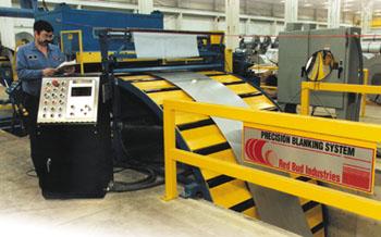 |
| Photo courtesy of Atlas Steel Products Co., Twinsburg, Ohio. |
If you have reviewed your existing equipment and processes as discussed in Part I of this article series and need to upgrade your flat-rolled processing further, you have a number of options that will be discussed in this article.
We also need to clarify nomenclature. I'm not sure what the difference is between a flattener and a straightener. No two people I've talked to seem to agree on a definition. In Europe they both are called levelers. Further, all flatteners are not the same. In this article, I will define my own terms to describe the different equipment configurations.
The Functional Difference Between Machines
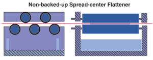 |
| Figure 1 This is the simplest roll configuration. These machines generally have five to nine large-diameter work rolls on spread centers, with a lot of daylight between them. They are supported by their end bearings only. |
Option No. 1: A non-backed-up spread-center flattener for surface-to-surface length differential. This is the simplest roll configuration and is illustrated in Figure 1. These machines have five to nine large-diameter work rolls on spread centers, with a lot of daylight between them. They are supported by their end bearings only; there are no backup roller supports. The work rolls are often nondriven. This is the least expensive configuration.
This machine is designed for removing coil set only. Rolls are configured to bend the material enough to achieve two yield strains, or twice the distance to the yield point in the outer fibers, or surfaces, of the metal. Thus, elongation past the yield point is strictly on the surface.
If we close the entry roll gap to get more bending, the unsupported center of the work rolls may deflect, putting edge waves into the metal.
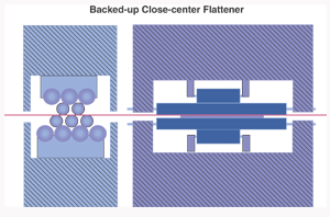 |
| Figure 2 This machine is the next step up from the non-backed-up spread-center flattener. The work rolls are smaller in diameter and closer together, and there is very little daylight between them. There are generally 11 to 19 of them—fewer for heavy-gauge, more for light-gauge material. |
Option No. 2: A backed-up close-center flattener for surface-to-surface length and width differential. This machine is the next step up in simplicity and is illustrated in Figure 2. The work rolls are smaller in diameter and closer together, and there is very little daylight between them. There are generally 11 to 19 of them—fewer for heavy-gauge, more for light-gauge material. They are usually driven. Backup rollers supported by massive top and bottom frames minimize work roll deflection under load.
To eliminate crosswise crossbow in addition to lengthwise coil set, this flattener configuration must be designed to produce four to five lengthwise yield strains in the outer fibers of the metal.
Option No. 3: A precision roller leveler for both surface-to-surface and edge-to-edge length differential. In a sense, a precision roller leveler (seeFigure 3) is similar to a backed-up close-center flattener. It should have the same size rolls and roll centers. Both have backup rollers. Again, there are generally 11 to 19 work rolls, and they usually are driven.
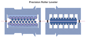 |
| Figure 3 A precision roller leveler is similar to a backed-up close-center flattener. It should have the same size rolls and roll centers. The difference lies in the ability to apply controlled roll bend through flights of adjustable backup rollers. |
Like the close-center machine, a precision roller leveler is also designed to produce four to five yield strains in the outer fibers of the metal. Again, yielding is more than a surface effect.
Unlike a flattener, leveler backup roller flights can be vertically adjusted independently of each other, so the work rolls can be bent deliberately in a controlled manner and held there under load. On a backed-up close-center flattener, the backup rolls are there to keep the work rolls from deflecting.
A leveler, in the neutral setting, like a backed-up flattener, can eliminate surface-to-surface length differentials such as coil set and crossbow.
Edge wave and center buckle are edge-to-edge length differential problems. For that we need to differentially elongate the center or the edges of the flat-rolled materials so that they are all the same length. This requires controlled work roll bend.
Of these three options, only a leveler with adjustable, independent backup rollers can control or eliminate edge-to-edge length differentials.
Machine Settings, Entry to Exit Gap
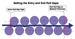 |
| Figure 4 In general, the entry gap is set tight, feathering out to approximately material thickness at the exit gap. The entry gap for any material thickness and yield strength usually is supplied by the equipment builder or designer. The entry gap for a spread-center flattener generally will be relatively light. The entry gap for a close-center flattener or leveler will be deeper. In all cases, the initial exit gap setting should be at material thickness. |
The process of setting the entry and exit work roll gaps is similar for all three machine types. In general, the entry gap is set tight, feathering out to approximately material thickness at the exit gap (see Figure 4).
The entry gap setting for any material thickness and yield strength usually is supplied by the equipment builder or designer. The entry gap for a spread-center flattener generally will be relatively light. The entry gap for a close-center flattener or leveler will be deeper. In all cases, the initial exit gap setting should be at material thickness.
At one operation I visited, operators were instructed to close the entry gaps enough to avoid slipping when pulling slit coil off an unpowered uncoiler. In all likelihood, that setting would be much too light to get much work out of the equipment. I recommended they refer to the equipment builder's manuals for the proper settings.
Once the entry roll gap has been set, final adjustment for lengthwise coil set, up or down, is done at the exit. If, as is usually the case, the last work roll is on the bottom, closing the gap slightly will induce additional upturn. Opening the exit gap slightly will give some downturn. If the last roll is on top, the opposite will be the case.
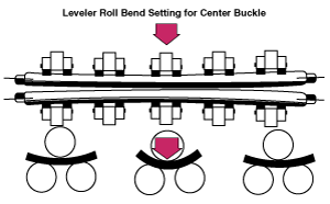
Machine Settings, Edge-to-Edge
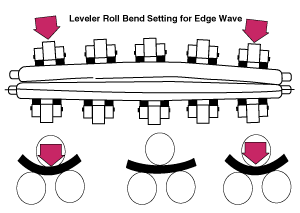 |
| Figure 5 In the case of center buckle or long center, you need to stretch the edges until they are the same length as the center. Set the backup rollers so the work rolls are tight on the edges and loose in the center. |
Neutral Setting. In the neutral setting, work rolls are straight and parallel, and the backup rollers are in a straight line, across the face of the machine. This is the setting if coil set or crossbow is the only shape problem. In practice, this would be the case with either a fixed backup flattener or an adjustable backup leveler.
Leveler Roll Bend Setting. Roll bend is available only with the leveler configuration. It is what makes a leveler a leveler. As a practical matter, most full-width, light-gauge levelers have from seven to 11 flights of entry-to-exit backup rollers, giving the operator considerable area control over waves or buckles in the incoming material.
The number and spacing of the backup roller flights are important. The more flights and the closer the spacing, the better. I've seen a machine with too few flights to hold the work rolls straight under load. The unsupported work rolls deflected between the flights.
To Stretch the Edges. In the case of center buckle or long center, you need to stretch the edges until they are the same length as the center (see Figure 5). Set the backup rollers so the work rolls are tight on the edges and loose in the center.
 |
| Figure 6 In the case of edge wave, or loose edges, you need to stretch the center until it is the same length as the edges. Set the backup rollers deep in the center and shallower on the edges. |
With the proper roll gap setting, the coil will not slip over the work rolls. The work rolls are all exactly round. The coil has to go a greater distance on the outer edges than in the center because the sink, or roll, mesh is greater on the edges. This means that we will stretch the edges in a controlled manner.
To Stretch the Center. In the case of edge wave, or loose edges, you need to stretch the center until it is the same length as the edges (seeFigure 6). Set the backup rollers deep in the center and shallower on the edges. Since the material will not slip and it has to go farther in the center, we will stretch the center and reduce or eliminate edge waves.
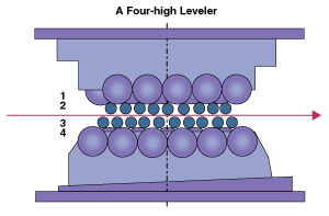
Four-high, Five-high, and Six-high Levelers
 |
| Figure 7 This is the most flexible configuration regarding shape control. However, the backup rollers may burnish the surface of the work rolls. This may leave a visible impression or stripe on some sensitive materials. On polished stainless or aluminum, or on class 1 automotive exposed stock, this surface imprint can be objectionable. |
The simplest leveler configuration is four-high (see Figure 7). This is the most flexible configuration regarding shape control. However, the backup rollers may burnish the surface of the work rolls. That may leave a visible impression or stripe on some sensitive materials. On polished stainless or aluminum, or on class 1 automotive exposed stock, this surface imprint can be objectionable. You can't measure it, but you can see it—it will show through paint or other coatings.
If such marking is a problem, a six-high leveler may be required (see Figure 8). Full-length intermediate rolls support the work rolls, and they in turn are supported by flights of backup rollers. A burnish mark on an intermediate roll does not transfer to the work roll—no striping problem! There is one drawback: This configuration can be very stiff. Roll bend may not be sufficient for optimum shape control.
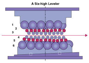 |
| Figure 8 If marking is a problem, a six-high leveler may be required. Full-length intermediate rolls support the work rolls, and they in turn are supported by flights of backup rollers. A burnish mark on an intermediate roll does not transfer to the work roll. |
Some processors compromise with a five-high leveler. The adjustable backup flights for cold-rolled coils usually are on the bottom work roll bank. The intermediate rolls on the bottom are eliminated, and the full-length intermediate rolls on the top are retained. This means we won't stripe the top surface of the coil, but we may stripe the bottom. As a rule, only one side of the coil stock is prime. With a five-high leveler, we have both the flexibility for area control and no striping on at least one critical side.
About Leveler Capacity
Your equipment builder should supply design capacities and settings for its machine for given materials, yield strengths, and thicknesses. But what happens when we run materials beyond these capacity limits?
If the material's thickness is below the machine's minimum limit:We will not flatten or level it. There is insufficient fiber elongation to make any permanent change in shape. No damage will be done to the equipment. Also note:
The lower thickness capacity rises in proportion to the yield strength.
There is another lower-limit issue: stiffness. If the material is so thin or soft that it does not push up and down on the leveler rolls hard enough to cause sufficient friction to avoid slipping over the rolls, the leveler cannot provide differential, side-to-side elongation. This can be the case with some perforated metals.
Perforating weakens the material and thus raises the upper thickness capacity. It is less obvious that with perforated metals the lower capacity may also rise because of the lack of stiffness.
If the material is very narrow:We run the risk of concentrating the entire load on too few backup rollers. You may bend or break the rollers or their supports. This is why there is no real narrow-thick capacity on this type of equipment.
If the material's thickness is above the machine's maximum limit:Loads on the equipment increase very quickly. Vertical separating forces between the upper and lower banks of work rolls are a function of the square of thickness. Don't do it! You may bend or otherwise permanently damage the machine's supporting structure. It is not a matter of how many times it has been overloaded. Once can do the job.
If the material's actual yield strength is higher than the machine's design yield:Machine loads increase as a function of the square of the actual yield strength.
Notice that I refer to actual yield strength, which may be much higher than the nominal yield strength. This is an easy trap. Many grades of metal have only minimum yield strengths, but their actual values can be 15 to 25 percent higher. That can be tough on the leveling equipment if you also are approaching maximum thickness at the same time.
As an example, if your machine's design capacity is based on 40,000 pounds per square inch (PSI) yield but the actual yield strength is 60,000 PSI, that is a (60/40)2 100 = 225 percent increase in the machine load. Maximum thickness capacity should be reduced by 100 divided by 225 percent, or by 44 percent.
The minimum thickness would be increased by (60/40) 100 = 150 percent. The minimum thickness rises and the maximum falls. You cannot produce four to five yield strains and cannot fully level any thickness outside the revised yield range on this particular machine. You may be able to produce sufficient yield strain to remove coil set.
About the Author

Eric Theis
About the Publication
subscribe now

The Fabricator is North America's leading magazine for the metal forming and fabricating industry. The magazine delivers the news, technical articles, and case histories that enable fabricators to do their jobs more efficiently. The Fabricator has served the industry since 1970.
start your free subscription- Stay connected from anywhere

Easily access valuable industry resources now with full access to the digital edition of The Fabricator.

Easily access valuable industry resources now with full access to the digital edition of The Welder.

Easily access valuable industry resources now with full access to the digital edition of The Tube and Pipe Journal.

Easily access valuable industry resources now with full access to the digital edition of The Fabricator en Español.
- Podcasting

In this episode of The Fabricator Podcast, Caleb Chamberlain, co-founder and CEO of OSH Cut, discusses his company’s...
- Trending Articles
1
AI, machine learning, and the future of metal fabrication

2
Employee ownership: The best way to ensure engagement

3
Steel industry reacts to Nucor’s new weekly published HRC price

4
Dynamic Metal blossoms with each passing year

5
Metal fabrication management: A guide for new supervisors
