


Everything you need to know about flatteners and levelers for coil processing—Part 4
New applications and options in flattening and leveling
 |
| Photo Courtesy of Atlas Steel Products Co., Twinsburg, Ohio. |
We can almost always improve the shape of the metal, but there are limits. If you have good material coming in, you can make it into superb material. If you have bad material coming in, you might make it into good material though probably not superb stuff. Get the best coils you can afford for your job.
Preventive Maintenance
Shape control equipment—flatteners or levelers—generally is the heart of most manufacturer's or service center's coil processing and feeding lines. Don't overload it. Use proper settings. Maintain it. Align it properly. Keep it clean and calibrated.
The surfaces of flattener or leveler work rolls and backup rollers should have been case-hardened to reduce wear. However, they can pick up slitter slivers, aluminum oxide, spelter, mill scale, and grit.
 |
| Figure 1 Work rolls can be cleaned with an abrasive cloth-covered wooden board designed so that it will not pass through the flattener or leveler side frames. |
To clean work roll surfaces, put a Scotch-Brite® pad, carpet, or other cloth fastened to a T-shaped plywood board (seeFigure 1) into the slowly turning but empty flattener or leveler roll nip and hold it there. The T should be wider than the machine frame so the board will not pass through.
Note that this roll cleaning can be dangerous; employees must be careful not to get dragged into the machine. An intriguing option, available from one of the leveler manufacturers, is to perform this roll cleaning by remote control so that operators aren't put at risk (see Figure 2).
Work rolls and backup rollers are expendable tooling. Regrind your work rolls more rather than less often. Work rolls and backup rollers must be reground as matched sets. If this is done regularly, only a minimum of material has to be removed with each regrind. On that basis you might get 10 to 12 regrinds out of a set.
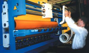 |
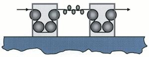
| Figure 2 With this hands-off roll cleaning device, a small coil of cleaning media is placed between the slowly turning work rolls. The machine then moves it back and forth across the face of the rolls. |
Light-gauge cut-to-length line rolls in service centers could be reground every six to 12 months. Slitters run a lot more miles of metal each day. Toll processors' slitting line leveling rolls may need to be reground every 10 to 30 days for use with sensitive-surface materials.
Most major leveler manufacturers offer an optional work roll cassette or "works in a drawer." You can pull a roll cassette in and out of the leveler as a unit. You may have more than one cassette. Flip the cassette open and clean it offline. This is generally an expensive option. We sometimes recommend it for a line that's going to run continuously, three or four shifts. For a conventional service center cut-to-length line, this expensive option may not be justified. For highly utilized toll processing operations, however, it might be worthwhile.
Another maintenance option is computer fault-finding diagnostics, and most new coil lines have this feature. I would not buy a coil line without it. The control monitor can tell you what's wrong with many items. In fact, it generally tells you what's going to go wrong before it does go wrong.
For instance, it can warn of drive motor and other overloads. If the machinery is approaching low oil level or low oil pressure, the monitor might warn you before a bearing freezes. Or it may tell you which circuit board in which panel is in trouble.
Other Options on New Levelers
Optional features on new levelers include automatic roll positioning for each thickness and material so the operator doesn't have to remember the settings. The computer remembers specific coils if you want to do rebooks. Note that for any given coil, the operator still has to make minor equipment adjustments to produce dead-flat material.
The addition of an automatic roll calibration control option simplifies calibration after roll changes to adjust for the newly reground roll diameters. Recalibration of a wedge-type mechanical leveler should be necessary only after roll regrinding. Regular calibration of a directly positioned hydraulic leveler apparently is required to compensate for drift.
Cut-to-length Line Configurations
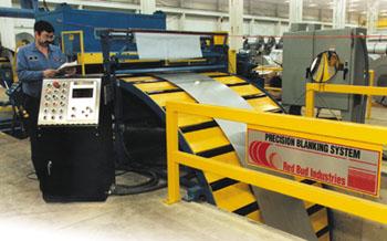
The most obvious and common application for leveling equipment is in a cut-to-length line.
In some very old lines, the leveler is placed after the shear, which means material is leveled in plate or sheet form. While this remains typical of many European lines today, it does have some technical problems. In North America almost all modern lines level the coil before the shearing operation. The arguments about the pros and cons of this are exhaustive, but I think North America has it right.
Except on some very heavy-gauge lines, you do not want to stop and start the leveler every time you feed to length into the shear, because this causes excessive wear on the leveler's drive train and probably leaves set marks on cold-rolled surfaces. Most lines use looping pits or flying shears with the leveler going slow then fast.
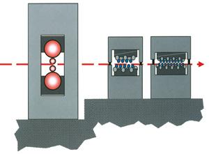
Since levelers have a limited capacity range of about four times the maximum or minimum material thickness, it is common for two levelers—a big one and a smaller one—to be used in a cut-to-length line to extend capacity range. Logic says that you then would have a two times four equals eight times the maximum or minimum thickness range, but that is not the case. Since minimum thickness rises with yield strength while maximum thickness is reduced, these lines need a considerable capacity overlap between their two levelers at nominal yield.
Remember that the equipment uses the actual yield strength, not the nominal. The practical range for two levelers is closer to six times maximum or minimum.
Some builders have offered a single leveler with two roll cassettes having different roll diameters and spacing. This arrangement still gives a capacity range of about six times maximum or minimum. It is also very complex and can cost almost as much as two separate machines.
A European builder has proposed a multiroll machine with vertically adjustable odd and even work rolls instead of the conventional, inline upper and lower banks. By backing off every other roll, the machines double the roll centers for the thicker range of materials. Some complexities remain in arranging backup flights. Most operators tell us that it takes several hours to swap cassettes.
There is also a question about placement of an edge trim slitter in a cut-to-length line. One argument is that it should be after the leveler for accurate width control. The contrary argument is that the edge trim slitter causes edge turn-down and thus should be before the leveler. I agree with the latter, provided there is a hefty center hold-down roll at the edge trimmer to avoid crossbow during trimming.
 |
| Figure 3 Powerful, large-diameter pinch rolls put tension on the coil in the roller leveler. This moves the neutral fiber closer to the inside radius of the metal's cross section. |
Capacities for Processing Heavier Thicknesses
Tension-assisted leveling lines can process heavier thicknesses than are practical with tension leveling. The issue is this: How deep past the yield point do we get penetration into the cross section?
Immediately following the cut-to-length line leveler, a pair of large driven pinch rolls provide pulling tension, thus moving the neutral fiber closer to the inside radius of the metal's cross section in the leveler as discussed previously (see Figure 3). The addition of some tension extends the maximum capacity upward and the minimum capacity downward. This is designed to provide increased leveling capacity range, increased stability, and improved leveling.
 |
| Figure 4 A temper mill teamed with conventional roller levelers can produce superb hot-rolled plate coil. |
A Temper Mill With Roller Leveling
A number of recent-model coil lines for heavy-gauge hot-rolled plate include a temper mill just before the leveler (see Figure 4). The effect on material surface quality, flatness, and stability is significant. This is especially important for applications in which some of the new technologies, such as laser cutting, are to be used. The material must stay flat during and after the cutting process.
The temper mill cannot get the material as flat as a corrective leveler can, and the leveler cannot get the material as stable or provide as fine a hot-rolled surface as the mill can. But the two together can produce some superb product.
Slitting Line Configurations Including Inline Leveling
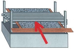
When we slit a coil with crown or a thick center, the center coils on the recoiler will have a larger OD than the outer coils. That causes the center strands to wind faster and the outer strands to wind slower and looser. The outer coils may be so loose that they are dangerous to handle.
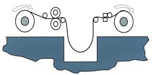 |
| Figure 5 A friction drag and looping pit-type slitter puts tension on all the strands, or mults, going onto the rewind mandrel. |
Years ago slitter operators stuffed paper into these outer coils so that they pulled tighter. That was very dangerous. ANSI B11.14 (American National Standards Institute) standards for slitting line safety, which apply to line owners and operators, specify you shall not stuff paper unless the line is stopped or the operator is protected. Paper stuffing no longer is necessary. Slitting technology has evolved with the drag and pit configuration.
A friction drag device following the slitter puts tension on all the strands, or mults, going onto the rewind mandrel. The apparent excess length on the outer, looser slit strands is allowed to hang down into a looping pit (see Figure 5) between the slitter and drag device. All strands going onto the recoiler are reasonably tight.
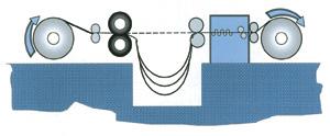 |
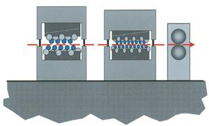
| Figure 6 Synchro-Wind and Kor-Flex slitting line configurations employ a pit, drag device, leveler, and recoiler. |
This solves the differential strand rewind issue but may introduce new problems. Aside from operators having to dig, clean out, and walk around the pit, the friction drag devices themselves can scratch or imprint the coil surface. In addition, coil shape and straightness cannot possibly be better than the master coil. Leveling individual narrow mults after slitting is neither mechanically nor financially feasible.
Leveling in a Slitting Line
Several different slitting line configurations are available that include corrective leveling after the slitter and before the recoiler. Synchro-Wind and Kor-Flex are similar (see Figure 6). Both employ a pit, drag device, leveler, and then recoiler. Neither significantly elongates the strands.
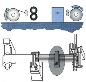 |
| Figure 7a and 7b A Strand Extensioner® slitter uses tension-assisted leveling to pull out camber, improve stability, and increase the thickness capacity range. |
The Strand Extensioner®, on the other hand, employs tension assist in the leveling process, which pulls out most of the camber, improves stability, and increases the thickness capacity range (see Figure 7). Significant necking, or narrowing, of slit strands has not been a problem. Since no friction drag is involved, the possibility of surface scratching is significantly reduced.
The line operator can stand at the main control panel, away from the dangerous recoiler nip, and change the amount of elongation in the tight mults so they all wind tightly with the flick of a control lever. Just as with a roller leveler, the line operator can elongate some parts of the coil relative to other parts by adjusting the backup roller flights to deliberately vary the sink or penetration of the upper and lower work rolls at different points along the face of the machine.
Tension Leveling
Tension leveling is an effective tension-assisted leveling method. The coil is put under significant tension between pull and drag bridles placed before and after the specially designed roller leveling device (see Figure 8). With tension leveling, all parts of the metal are pulled past the yield point, top to bottom, edge to edge. The full cross section is elongated a fraction of a percent. All the previous history of trapped stress is deleted. The material should be dead flat and relatively free of internal stresses.
 |
| Figure 8 A tension leveler pulls all parts of the metal past the yield point, top to bottom, edge to edge. The full cross section is elongated a fraction of a percent. |
Tension leveling usually is restricted to gauge thicknesses of metal. Because of the massive equipment and horsepower required, this process usually is not practical for thicker, hot-rolled plate coils. However, more and more service centers are using tension leveling lines to process cold-rolled steel and aluminum products.
How Flat Is Flat?
Measuring flatness, or even describing it, has been a tricky issue. Out-of-flat tolerances have been described by ASTM International and ANSI standards as a maximum wave height in 8 feet without any mention of the number of waves. When we're trying to fit up a fabrication, it makes a lot of difference whether we are talking about a 1/4-inch rise in 8 ft. or in every 8 in. We find increasing acceptance of the I-unit flatness designation (see Figure 9), which takes into account both wave height and wave length.
 |
| Figure 9 The I-unit flatness designation increasingly is being accepted as a measure of flatness. It takes into account both wave height and wave length. |
Producer mills say they can get less than 15 I units of flatness coming off the cold mill. With a temper mill, they can get less than 10 I units. A roller leveler, a Strand Extensioner, or a tension leveler produces less than 5 I units, and maybe less than 1 I unit. That's a big difference in flatness.
Scotch-Brite® is a trademark of 3M. Strand Extensioner® is a trademark of Herr-Voss Corp. Kor-Flex is patented by Pro-Eco.
American National Standards Institute, 1819 L St. N.W., 6th Floor, Washington, DC 20036, 202-293-8020, www.ansi.org.
ASTM International, 100 Barr Harbor Drive, West Conshohocken, PA 19428, 610-832-9585, www.astm.org.
About the Author

Eric Theis
About the Publication
subscribe now

The Fabricator is North America's leading magazine for the metal forming and fabricating industry. The magazine delivers the news, technical articles, and case histories that enable fabricators to do their jobs more efficiently. The Fabricator has served the industry since 1970.
start your free subscription- Stay connected from anywhere

Easily access valuable industry resources now with full access to the digital edition of The Fabricator.

Easily access valuable industry resources now with full access to the digital edition of The Welder.

Easily access valuable industry resources now with full access to the digital edition of The Tube and Pipe Journal.

Easily access valuable industry resources now with full access to the digital edition of The Fabricator en Español.
- Podcasting

In this episode of The Fabricator Podcast, Caleb Chamberlain, co-founder and CEO of OSH Cut, discusses his company’s...


