


Graduate Research Assistant, ERC/NSM
The quality of deep drawn sheet metal products is determined largely by the rate at which a sheet is drawn into a die. Varying blank holder force (BHF) as a function of time or the press stroke is of great importance.
In the beginning of a deep drawing stroke, wrinkling of the sheet can become a problem, and the BHF should be relatively large to guard against it. As the drawing continues, the flange area thickens, and wrinkling becomes less likely. At the same time, however, the fracture limit can be reached, and the part may fail unless the BHF is reduced and more material is allowed to draw into the die.
Properly controlling BHF increases the limiting draw ratio (LDR), achieves greater draw depths, reduces the number of intermediate forming dies required, and improves the quality of deep drawn parts. The availability of flexible control will have important implications for difficult-to-form materials such as aluminum and stainless steel. This is especially for small production lots.
Elastic spring elements such as helical, cup, rubber, and polyurethane springs are used commonly in the design for tooling used to form both sheet and coil. In addition, gas systems such as air cushions or nitrogen cylinders are used extensively.
These devices produce a linearly increasing force proportional to the press ram displacement. Thus, the spring elements work contrary to all desired constant or decreasing BHF patterns suggested by many researchers.
Draw beads still are the main BHF control method used in automotive stamping. Some success has been reported in controlling the draw bead restraining force in time by varying the draw bead penetration in a laboratory test apparatus.1Hydraulic cushions provide reliable control of BHF over the stroke time. BHF is transmitted from the cushion to the blank holder through the cushion pins.
Unfortunately, slight variations in the lengths of the pins result in uneven transmission of force by each pin. This, in turn, results in tilting and deflection of the tooling, thus producing an unpredictable, nonuniform blank holder pressure pattern between the blank holder and the sheet metal blank. Several design options have been suggested to adjust the length of each cushion pin independently during the forming process,2but this leads to quite complex and costly systems.
Flexible BHF control currently is available commercially on large transfer presses equipped with various multiple-point pressure control systems that apply adjustable force to blank holders. In these presses, BHF can be adjusted about the periphery of the blank holder as a function of location and time (or ram position). Most of these systems use independently controlled hydraulic cylinders.
All hydraulic systems use an external source of hydraulic power, which includes a motor, pump, fluid reservoir, filters, long pipelines, etc. Each cylinder has a sophisticated servo-valve-based, closed-loop CNC. Multiple in-die sensors monitor the forming process.
Also, a gas pressure control system similar to the hydraulic systems discussed earlier has been developed for nitrogen cylinders.3
A single-cylinder laboratory prototype of the hydraulic/nitrogen BHF control system has been built in collaboration with a private company and tested at the Engineering Research Center for Net Shape Manufacturing (ERC/NSM) at The Ohio State University in Columbus (see Figure 1).
The control valve used for the prototype is a high-performance, feedback-type proportional valve designed to provide both directional and flow control according to the electric reference signal.
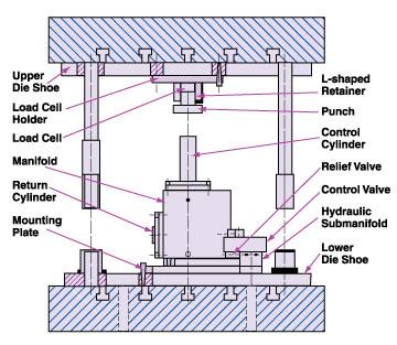 |
| Figure 1: The prototype system was equipped with a feedback-type proportional valve and demonstrated that even with a simple open-loop gain control, force profiles could be generated to improve deep drawing operations. |
The system prototype was developed to determine the system's application range and performance characteristics experimentally and to evaluate the feasibility of the design concept. Therefore, no effort was made to model the dynamics of the system analytically or to design a feedback controller to improve system performance. Rather, the simplest open-loop gain control strategy was chosen.
Open-loop control usually has been preferred by the metal forming industry because of the performance of in-die sensors required for feedback control in a closed-loop system and the high cost of control engineering.
After experimental data from transient and frequency response for an open-loop system is obtained, it is possible to generate an empirical model of the system's dynamics and design a closed-loop control system of any level of sophistication. The latter is beyond the scope of this work, however.
Because no blank holder actually was present in the experimental system, the BHF will be referred to in this article as the control cylinder force (CCF).
The control cylinder is placed directly under the load cell punch (see Figure 1). As the punch descends during the press ram stroke, the hydraulic fluid in the control cylinder is forced through a proportional valve, the opening of which is controlled electronically via a signal sent from the data acquisition system (DAS).
The signal controls the spool position within the valve in time and hence, for a given punch velocity, governs the pressure in the control cylinder, which resists the punch motion with a corresponding force. This force is measured directly by the load cell and recorded as a function of time by the DAS.
If the pressure resulting from throttling in the proportional valve becomes too large, the fluid may bypass the proportional valve and flow through the relief valve. The flow from either of these valves then is routed into the return cylinder, where it is stored until the press ram begins to ascend.
The nitrogen chamber of the return cylinder is connected to the nitrogen pressure tank so that the pressurized nitrogen then provides the force that restores the control cylinder, via the check valve, to its original position.
In addition, by varying the nitrogen pressure in the return cylinder, one may control the return speed of the system explicitly. The return cylinder and the nitrogen gas tank compose essentially a nitrogen-charged, piston-type accumulator; the control cylinder could be replaced with a conventional single- or double-action hydraulic cylinder.
The experimental system has the following distinctions:
The relief valve was set to open when the CCF exceeded 6 tons. This way, a family of calibration curves (CCF versus control signal voltage for each constant press speed) was obtained.
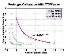 |
| Figure 2: Calibration data for three press speeds showed that curves grew increasingly steep as press speed was reduced. |
Figure 2 shows the calibration results for three different press speeds: the lowest, 6.2 millimeters per second; intermediate, 25 millimeters per second; and the highest, 68 millimeters per second. The curves are nonlinear and grow increasingly steep as press speed is reduced.
This indicates that for the selected valve size the fluid flow is too low at low speeds for variations in the orifice opening to be consequential until it is almost closed. At the highest speeds, the range over which the CCF reasonably can be controlled is quite large.
This is compelling evidence that the flow rates must be known before an appropriate flow control valve may be selected. Instead of trying to cover all possible press speeds, selecting a valve for a particular forming operation results in a better-performing control system. Because the highest press speed was the most accurate reflection of actual deep drawing processes and represented the most challenging control problem, all other experiments were conducted at this speed.
Numerous step signal responses were obtained with various step widths in time and various step heights. This experiment allowed researchers to evaluate the system's transient response characteristics such as rise time, settling time, and overshoot.
In addition, these tests simulated a stepwise change of the BHF in a deep drawing process. Because force increases are not very important for deep drawing, the experiments concentrated on stepping down the CCF. Ramped changes in BHF also have important implications for deep drawing.
 |
| Figure 3 |
Because ramped increases are attainable with springs, the experiments were focused only on ramping down. A series of CCF ramps starting and ending at different tonnages was tested. All of the experiments were conducted with the nitrogen pressure in the return cylinder set at 20 bar and the press force set at 90 tons.
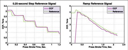
Figure 3 summarizes the test results for the BHF control system prototype with the feedback-type valve. Figure 4 shows two examples of the prototype system response to a ramp and to a 0.25-second step signal. The response curves follow the reference input closely, with a small steady-state error. This error is introduced by curve fitting the calibration data (see Figure 2) with a simple power function.
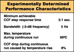
For any system that is to be run continuously, knowing the temperature changes over time is important. In the case of the BHF control system prototype, it was important to ensure that the temperature of the valve was below the maximum given by the manufacturer's specifications (80 degrees Celsius) and to determine whether the heating of the fluid resulted in any significant changes in CCF.
The control signal was set to give 4.2 tons of CCF (the upper third of the prototype operating range). The press was run continuously at the maximum stroke rate of about 18 strokes per minute (SPM). The temperature was measured with analog magnetic surface thermometers attached to the external surfaces of the control cylinder and the proportional valve.
Researchers expected CCF to drop slightly as a result of the fluid viscosity reduction as the temperature of the fluid increased. Figure 5 shows the results of temperature measurements taken every 50 strokes during a continuous run until the system reached steady state and the temperature stopped increasing.
| Figure 4: The response of the BHF control system to a 0.25s step (a) and ramp signal (b) are shown here. |
The changes of the CCF also were monitored during the whole run. The two temperature curves have the same basic shape, with the valve temperature taking somewhat longer to reach steady state.
The final temperature was 55 degrees Celsius at the control cylinder and 66 degrees Celsius at the proportional valve. That is below the maximum specified value for the valve (80 degrees Celsius). The CCF dropped about 8 percent during the run as the fluid reached a steady temperature after about 650 strokes. Therefore, if the system is to be used continuously at a high stroke rate, temperature compensation should be built into the system control algorithm.
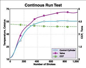 |
| Figure 5: The experiments showed no appreciable change in CCF as fluid warmed to its steady-state temperature. |
Based on the experiments, control valve selection is the most critical step in designing a hydraulic/nitrogen BHF control system. Proportional valves with an internal feedback loop on spool position are required for the system to control BHF in time successfully. The BHF control system prototype equipped with a feedback-type valve demonstrated a fast, stable, and repeatable response and proved that even with the simple open-loop gain control, force profiles capable of greatly improving deep drawing operations can be generated. System performance can be improved further by designing a controller that includes an empirical dynamic model of the system.
The authors cite the following references in the preparation of this article:
1. J. R. Michler, A. R. Kashani, M. L. Bohn, and K. J. Weinmann, "Feedback Control of the Sheet Metal Forming Process Using Drawbead Penetration as a Control Variable," Transactions of NAMRI/SME, Vol. XXIII (1995).
2. K. Siegert and M. Klamser, "Hydraulische Vielpunkt-Zieheinrichtungen im Pressentisch einfach wirkender Pressen (Hydraulic Multiple-point Draw Assemblies for Single-action Presses)," in proceedings of the Conference on Draw Systems for Single Action Presses for Sheet Metal Forming, sponsored by Technical University of Stuttgart, 1991.
3. M. Schlegel, "Pressure Controlled Nitrogen Cylinders for Draw Dies," Journal of Material Processing Technology, Vol 46 (1994), pp. 505-518.


The Fabricator is North America's leading magazine for the metal forming and fabricating industry. The magazine delivers the news, technical articles, and case histories that enable fabricators to do their jobs more efficiently. The Fabricator has served the industry since 1970.
start your free subscription
Easily access valuable industry resources now with full access to the digital edition of The Fabricator.

Easily access valuable industry resources now with full access to the digital edition of The Welder.

Easily access valuable industry resources now with full access to the digital edition of The Tube and Pipe Journal.

Easily access valuable industry resources now with full access to the digital edition of The Fabricator en Español.
In this episode of The Fabricator Podcast, Caleb Chamberlain, co-founder and CEO of OSH Cut, discusses his company’s...


