


Feed to registration
A different way to process round, nested parts efficiently
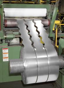 |
| Figure 1 In the mid-1980s service centers attempted to create coils slit in a scroll pattern to reduce scrap. |
When processing round or nested parts, most stampers use one of these three methods with varying degrees of scrap rates:
- Conventional coil stock feeding into a one-out die. This method results in an extremely high scrap rate.
- Coil stock feeding into a multiple-out die. This technology results in greater material savings than one-out dies, but tooling costs are higher and more press tonnage is needed.
- Zigzag or stagger feeding. Material is fed along the leading edge and X axis into a one-out die. After one stroke, the feeder traverses along the X and Y axes, positioning the appropriate-width coil into line with the die. This movement typically is accomplished with an additional servomotor turning a ball screw to provide accurate positioning. Tooling may require modification to allow strip to traverse along the die.
In the mid-1980s service centers attempted to create coils slit in a scroll pattern to reduce scrap (see Figure 1). In a scroll pattern, a radius is slit into the edge of the strip approximating the size of a finished round stamping. This sounds simple enough; however, at the time servo feed technology could not accurately feed material, and accumulative errors led to failure. After multiple progressions, the built-up inaccuracies caused overlap from one part to the next.
At that time the concept was scrapped ... until now.
Feed to Registration
Improved servo feed technology has enabled stampers to feed scroll-slit material accurately, which is known as feed to registration.
This scrap-reducing process can result in material savings compared with a one-out die, but it works only for certain applications. For example, a die must be a single-station one-hit or progressive transfer die in which the first station is detached from the main strip. The process will not work with a true progressive die because of variations in scroll-slit blanks, and material must be less than 0.090 inch thick.
To justify equipment and tooling costs, a stamper needs to run high volumes or high-cost material, such as stainless steel or aluminum. This process is suitable for motor laminations, oil filters, propane cylinders, and oil seals.
How It Works
The first step of this process is for the steel processor to machine the slitting knives according to the specifications for the finished pattern. The steel processor installs these knives on a customized, tight-tolerance head on a conventional slitting line. This equipment is used to slit and rewind coil material with the scroll pattern.
The problem with past attempts involved the accurate feeding of material into the die area. As described earlier, accumulative errors inherent in servo-feeding and strip variations were the cause of prior failures. A servo feed had to be engineered to feed accurately without accumulative error from part to part and no reduction in parts per minute.
The servo feed developed for this application uses sensor technology. As the material is fed, the sensor registers the leading edge and compares any difference from one length to the next. Then the drive's microprocessor compensates and adjusts the next feed length to eliminate any accumulative error from part to part. As a result, feed lengths can be held to within 0.010 in. on scrap exiting the die. Scrap lengths can vary while the finished part is still within tolerance. Feed length variations of 0.020 in. are being reported on slit strips while still maintaining accurate progressions.
Because the sensor is in a fixed location, material guiding is critical in the feed to registration process. The leading edge must be presented in the same spot on each progression for the sensor to provide repeatability. Stampers will need to develop guiding parameters to ensure the strip remains on the same plane.
Servo feed design also is critical, especially for processing light-gauge material, such as 0.020 in. to 0.060 in. Although the dies in this application do not use pilots, the feed rolls still can be lifted on each press stroke at bottom dead center. Minor camber in light-gauge material may cause the metal to ride up or crowd on the edge guides (this problem is minimal with heavier-gauge material, such as 0.060 in. to 0.090 in.). Lifting or piloting the feed rolls ensures any minor camber in the material is released, allowing the material to relax and lie flat again.
When the roll is lifted, if the upper and lower feed rolls come out of parallel, troubles ensues! Any nonparallel situation will create a pinch point on either end of the feed roll. The result is a "steering" of the material in the direction of the pinch point. This creates havoc when attempting to present the leading edge to the sensor uniformly for each and every progression. If any steering of the material occurs, the metal will buckle, which adversely affects the sensor's material registration. The desirable mechanical design employs an upper roll that pivots over the lower roll to ensure consistent roll parallelism.
For applications such as clutch disks, oil seals, oil filters, and other round stampings, feed to registration with scroll-slit material can reduce scrap rates and, in some cases, eliminate the need to retool the job. This method is proving to be an efficient and effective way to produce parts while minimizing scrap.S
Tim Qualls is regional sales manager with P/A Industries Inc., P/A Technology Park, 522 Cottage Grove Road, Bloomfield, CT 06002-3191, 877-243-1959, fax 860-242-4870, sales@pa.com, www.pa.com.
About the Publication

subscribe now

The Fabricator is North America's leading magazine for the metal forming and fabricating industry. The magazine delivers the news, technical articles, and case histories that enable fabricators to do their jobs more efficiently. The Fabricator has served the industry since 1970.
start your free subscription- Stay connected from anywhere

Easily access valuable industry resources now with full access to the digital edition of The Fabricator.

Easily access valuable industry resources now with full access to the digital edition of The Welder.

Easily access valuable industry resources now with full access to the digital edition of The Tube and Pipe Journal.

Easily access valuable industry resources now with full access to the digital edition of The Fabricator en Español.
- Podcasting

In this episode of The Fabricator Podcast, Caleb Chamberlain, co-founder and CEO of OSH Cut, discusses his company’s...


