


Flatness in coil processing operations: New turns in the leveling process
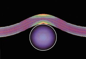 |
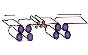
| Figure 1: The different colors shown here indicate how much force or stretching is involved in bending metal over a roll without strip tension. |
Precision Roller Leveling With Tension
Some coil processing lines now add tension to the leveling process. This process extends the lower capacity range of the precision roller leveler, produces greater stability in the metal, and may even make the metal flatter.
In a roller leveler, the material is alternately bent up and down, stretching the outside and compressing the inside of each bend. On the first bend, the bottom is stretched and the top is compressed; on the second bend, the bottom is compressed and the top is stretched, and so on. The neutral area in the middle is neither elongated nor compressed past the yield point. Permanent change in the metal is strictly on the surfaces.
A computer analysis of tension and compression forces is shown in Figure 1. The different colors indicate how much force or stretching is involved in bending the metal over that particular roll diameter. The stresses or force, and therefore the strain or stretching, are symmetrical about the center of the cross section.
The yellow, green, and purple areas are completely symmetrical about the neutral fiber (the center part that is neither compressed nor stretched). The yield point is exceeded in the red areas. Where it is yellow, the material is right at yield point. In the blue and green areas, the material is in the elastic range, and no permanent change has been made.
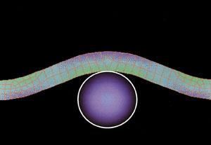 |
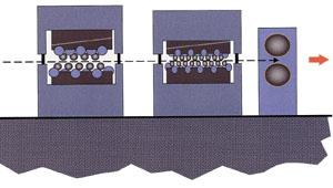
| Figure 2: The computer analysis shown here indicates the level of force or stretching that is found when tension is applied to the strip. |
Putting the material under tension as it goes through the flattener or leveler moves the neutral fiber toward the inside of the bend. The strip tension adds to the bending tension on the outside of the bend. It subtracts from the bending compression on the inside of the bend. There is less compression on the inside and more tension on the outside. Therefore, less elongation occurs on the inside of the bend, while more occurs on the outside of the bend. The neutral fiber moves toward the inside radius of the bend.
Figure 2 shows the computer analysis again, this time with tension on the strip. This time the stress pattern is not symmetrical. With the material under tension, the neutral fiber moves toward the inside of each bend, first toward the top surface, then toward the bottom surface in the next bend, then toward the top surface again, and so forth. The process is reversed again and again as the material progresses through the flattener or leveler. By the time the metal exits the machine, it has exceeded its yield point on more or possibly all of the cross section, not just the top and bottom surfaces.
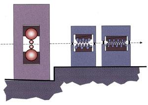 |
| Figure 3: A pair of large driven pinch rolls provides tension immediately following the leveler. |
Leveling with tension assist can go up to 1/2-inch or even 5/8-inch thickness capacity, which would be difficult with a tension leveler. The depth into the cross section at which the yield point is exceeded depends on the amount of tension. In the installation shown in Figure 3, a pair of large, driven pinch rolls provides tension immediately following the leveler. An on-the-fly cut-to-length shear follows the pinch rolls.
On-the-fly shearing eliminates the need to stop the line for the cut. For example, it may not be practical to loop heavy plate coil, but if the line is stopped for cutting, whether under tension or not, a set mark could be made on the material surface. Also, tension in the leveler would be loosened, resulting in leveling discontinuity. This can be avoided by using on-the-fly, nonstop shearing. The line in the lead-in photo completes a 5,000-pound sheet lift in less than 30 seconds.
Leveling in the Slitting Process
What about leveling in slitting lines? If a coil that has a typical crown or thick center is slit, the center mults on the recoiler will have a larger diameter than the outer mults. That makes the center mults wind quicker, while the outer mults wind slowly and more loosely, with the apparent excess hanging down into a loop.
Years ago, paper would be stuffed into these loose outer mults so that they would act as though they were the same diameter as the center cuts, winding tightly in the process. Today, the American National Standards Institute (ANSI) B11.14 standards for slitting safety, applying to line owners and operators alike, prohibit paper stuffing unless the line is stopped or the operator is protected. Stuffing paper or cardboard is no longer necessary because slitting technology has eliminated the need to do it.
Thirty years ago, friction drag devices were developed to put tension on all the strands or mults going onto the rewind mandrel.
The apparent excess strand on the outer, looser mults was allowed to hang down into a looping pit between the slitter and drag device. That solved the differential strand rewind issue but introduced new problems. Aside from having to dig, clean out, and walk around the pit, any dirt or grit in the friction drag devices could scratch or imprint the coil surface.
In addition, coil shape and straightness could not be better than the master coil, and was often worse. Leveling individual narrow mults after slitting was neither mechanically nor financially feasible.
Slitter-induced cross bow is another problem. It will not occur in a perfect setup: the male and female stripper rings are exactly right, the slitter knives are sharp and set up correctly, and the slitter arbors do not deflect. Of course, most setups are not perfect.
An imperfect slitter setup puts alternating up/down cross bow into each piece. The first cut pushes from the male down into the female. The second cut pushes from the male up into the female, then down, up, etc. The result is individual mults with alternating edges up and edges down. This is a problem for critical stamping applications, roll forming, and tube making because the up-bow mults do not run parts quite the same as the down-bow mults do.
Stampers, tube makers, and roll formers sometimes ask the slitter to rotate every other slit mult 180 degrees so all the burrs and cross bows are in the same direction, in hopes that this will solve the problem, at least on narrow strands. What actually happens is that the master coil comes from the mill with cross bow, and that cross bow adds to the cross bow from the slitter on the first cut, subtracts from it on the second cut, adds to it on the third cut, etc. The result is one mult that is bowed, one that is flat, one bowed, one flat, and so on. Rotating or twisting alternate slit mults 180 degrees will not eliminate this problem, but it will put all the slitter burrs in the same direction.
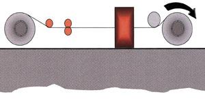 |
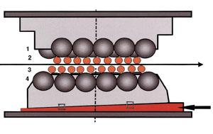
| Figure 4 Leveling with tension assist of each strand immediately after slitting and before recoiling can help control many of the problems associated with cross bow. |
A Nonconventional Slitting Process
Leveling with tension assist of each strand immediately after slitting and before recoiling can help eliminate these problems. That is what Strand ExtensionerTM, a proprietary slitting process developed by the author's company, does. This particular slitting line configuration was originally developed to elongate the thicker center strands that would otherwise recoil faster and tighter. When this process is used, all strands rewind tightly without dangerous paper stuffing or a friction drag device and looping pit. Most of these lines sit on a flat floor.
With this process, the line operator stands at the main control panel, away from the dangerous recoiler nip, and changes the amount of elongation in the tight mults by flipping a control lever. Just as with a roller leveler, the operator can elongate some parts of the coil relative to other parts by adjusting the backup roller flites to deliberately vary the sink or penetration of the upper and lower work rolls (see Figure 4) at different points along the face of the machine.
On a conventional slitter, splitting a coil with a thick or crowned center results in two cambered strips curving toward each other on the recoiler. They squeal as they bind against the overarm separator on a pull-through line. Sometimes, a scrap center cut can prevent this problem. The slit mults can be steered onto the recoiler with a drag and pit line, but there are still two cambered halves. With this proprietary process, the center can be stretched, steering the two halves on the recoiler, without the help of a separator at the recoiler and without making a scrap center cut.
 |
| Figure 5: In tension leveling, the coil is put under significant tension between pull and drag bridles placed before and after the roller-leveling device. |
Tension Leveling
In tension leveling, the coil is put under significant tension between pull and drag bridles placed before and after the roller leveling device (see Figure 5). With tension leveling, all parts of the metal are pulled past the yield point, top to bottom and edge to edge. All the previous history of trapped stress should be deleted. The material should be perfectly flat and relatively free of internal stresses.
Tension leveling usually is restricted to the gauge thickness of metal. Because of the massive equipment and horsepower involved, full tension leveling usually is not practical for thicker hot-rolled plate coils. However, more and more tension leveling lines are being found processing cold-rolled steel and aluminum products in toll processors and service centers.
 |
| Figure 6: A temper mill and matched precision leveler can produce plates that are entirely flat and stay that way. |
Trapped Stresses and Stability
A temper mill and matched precision leveler (see Figure 6) can produce plates that are entirely flat and stay that way. That is an important issue for working with heavy material.
Fabricators who use laser burning tables or turret punch presses want to ensure that their parts will stay flat. If trapped stresses are released by cutting or heating, the material will not stay flat. A temper mill in a cut-to-length line is primarily for surface effect, but used in conjunction with roller leveling, it can affect part stability and surface quality.
A temper mill can be used to flatten material, although not as effectively as a leveler. The temper mill primarily hardens the surface, raising its yield point without elongating it lengthwise, resulting in a better, smoother hot-rolled plate surface. It also increases the amount of elongation required to get beyond the elastic limit at the surface.
When plate is bent in a leveler, the surfaces are stretched or compressed in direct proportion to the distance from the neutral centerline. When the plate is unbent, that stretching and compression are reversed, also in direct proportion to the distance from the centerline. The problem with this reversal process is that where the metal surface has been forced past its yield point, it does not want to go back to zero, which means trapped internal stresses have been added. The random trapped stress in the received mill material may have been traded for a more consistent trapped stress, but it has not been eliminated.
The temper mill, on the other hand, raises the surface hardness of the metal, without lengthwise elongation, before the roller leveling process. Now, when the plate coil is bent over the leveling rolls, the extension required to exceed the yield point and permanently change the length of the surface relative to the core is higher than that required below the surface. Thus, the surfaces have no problem reverting to their original semiflat condition, and the remaining trapped stresses are minimized. The result is flat plate and stability.
The trapped stresses that come from the mill are variable and random. They are not consistent from one edge of the coil to the other, or from one end of the coil to the other.
A nonbacked-up flattener is used primarily for controlling coil set or longbow, an outer surface effect. Trapped stresses remain in the middle, so the metal is not stable. With a precision leveler, the yield point is exceeded about 80 percent of the way from the top and bottom surfaces toward the center. Only the 20 percent of the thickness in the middle has not exceeded the yield point, and thus it is much more stable. The addition of tension assist to the leveling process increases the depth of the yielding effect in the metal cross section. Adding a temper mill to a heavy cut-to-length line further reduces the remaining trapped stresses.
 |
| Figure 7: Recently, the I-unit of flatness designation, which takes into account both wave height and wave length, has been gaining more acceptance. |
How Flat Is Flat?
Measuring, or even describing, flatness has been a tricky issue. In the past, ASTM flatness tolerances have described a maximum height of wave in 8 feet, without any mention of the number of waves in those 8 feet. In fabrication fit-up, it makes a lot of difference whether there is a 1/8-inch rise in 8 feet, or in every 8 inches. Recently, the I-unit of flatness designation (see Figure 7), which takes into account both wave height and wave length, has been gaining acceptance.
A cold mill can get less than 15 I-units of flatness. Coming off a temper mill, material may have less than 10 I-units. With a roller leveler, tension-assisted leveler, or tension leveler, the number may be 5 I-units, and possibly less than 1 I-unit. That is a big difference.
Leveler Maintenance Options
Keeping leveling equipment cleaned and well maintained is important. Options are available to help simplify maintenance work on these machines.
Most manufacturers offer optional work roll nest cassettes. These leveler cassettes can be pulled in and out of the leveler as a unit. More than one cassette may be used, sometimes with different roll diameters. Different cassettes can be put in, or they can be flipped open for cleaning, off-line. This option is recommended for production lines that will run continuously for three or four shifts. It is also recommended when leveling with tension assist of each strand after slitting because this method runs more coil in a given period of time. For a conventional service center cut-to-length line, this option may not be necessary. For a toll processor, it may be more attractive. Another option is a leveler with a roll-open top. The top frame opens like a book, either mechanically in the case of smaller machines or with hydraulic lifts. It is quick and exposes both the upper and lower roll banks for easy cleaning.
The simplest roll cleaning aid is an extra-high, wide-opening top frame. The upper leveler frame opens vertically to about a 4-inch gap so that cleaning equipment can work on the rolls.
Four-High, Five-High, and Six-High Levelers
The basic roller leveler is a four-high configuration. This is the most flexible from a shape control point of view. The back-up rollers will not wear grooves in the glass-hard work rolls under normal use, but they can burnish the surfaces of the work rolls. This burnish mark may leave an impression on the surface of soft, polished, or other flat-rolled materials. Although the impression is too small to measure, it is visible.
If such marking is a problem, a six-high leveler might be an appropriate choice. Full-length intermediate rolls support full-length work rolls, and they in turn are supported by flites of back-up rollers. A burnish mark on the intermediate roll does not transfer to the work roll. This configuration can be very stiff, and roll bend control may not be sufficient for optimum shape control.
On a five-high leveler, on which the back-up roller flite adjustment wedges usually are found, the intermediate rolls are eliminated but retained on top. On the bottom, the work rolls and their back-up roller flites give better roll bend flexibility for improved flatness control. On the top, the full-length intermediate rolls are retained between the work rolls and the back-up rollers to avoid striping. This means that the top surface of the coil will not be striped, but the bottom may be. Usually, however, only one side of a coil is critical.
Options on Levelers
Many of the newer levelers include operator's stations that hang from pendants or are mounted on swing-out hinges for easy control positioning at the machine exit. Other control features may include the following:
- Automatic roll positioning "remembers" settings. It can remember specific coils if the operator wants to do re-books. The operator can ask the machine to go to 10-gauge cold-rolled steel, the coil from the second shift at a certain mill, and the control will remember the settings from the last time the operator ran that material and will go to that position automatically.
- Automatic calibration simplifies recalibration after roll changes to adjust for changes in roll diameter. A properly designed leveler should not need recalibration between roll changes.
- Computer fault-finding diagnostics show on a screen what is wrong with a coil line. They generally indicate, on some items, what is going to go wrong before it does. For instance, if the oil level or pressure is low, the diagnostics will indicate that before lubrication runs out.
Summary
The addition of tension assist to the leveling process in cut-to-length or slitting lines can extend the capacity range and improve material stability. A temper mill paired with a leveler can also improve surface condition and hardness and further enhance stability. A number of options on newer equipment are designed to make operation, maintenance, and roll cleaning easier.
About the Author

Eric Theis
About the Publication
subscribe now

The Fabricator is North America's leading magazine for the metal forming and fabricating industry. The magazine delivers the news, technical articles, and case histories that enable fabricators to do their jobs more efficiently. The Fabricator has served the industry since 1970.
start your free subscription- Stay connected from anywhere

Easily access valuable industry resources now with full access to the digital edition of The Fabricator.

Easily access valuable industry resources now with full access to the digital edition of The Welder.

Easily access valuable industry resources now with full access to the digital edition of The Tube and Pipe Journal.

Easily access valuable industry resources now with full access to the digital edition of The Fabricator en Español.
- Podcasting

In this episode of The Fabricator Podcast, Caleb Chamberlain, co-founder and CEO of OSH Cut, discusses his company’s...
- Trending Articles
1
AI, machine learning, and the future of metal fabrication

2
Employee ownership: The best way to ensure engagement

3
Steel industry reacts to Nucor’s new weekly published HRC price

4
Dynamic Metal blossoms with each passing year

5
Metal fabrication management: A guide for new supervisors
