


Getting a handle on coil handling
One size doesn't fit all when selecting coil handling equipment
 |
The initial objective in selecting coil handling equipment is to determine the type of system best-suited to the application. Requirements—such as production rates (feed length versus strokes per minute), material finish and condition, available shop floor space, tooling, material yield strength, partial-coil operation, and required changeover time—all play important roles in the selection process.
Newcomers to metal fabricating and forming might find such equipment decision-making complex, but technical advances in manufacturing have contributed to the development of more competitively priced machines that are much more accurate and flexible than previous generations. As a result, the search for coil handling equipment falls into one of two categories: combination spacesaver-type systems and conventional coil handling systems comprising individual pieces of equipment.
It's important to understand what the equipment does, so that you can choose the right coil handling system for your application.
A Combination Look
A coil stock handling system performs three basic functions: uncoiling, straightening, and feeding.
 |
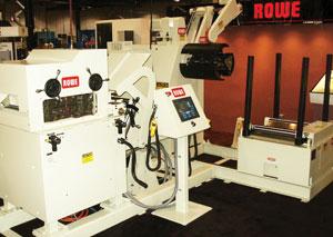
| Figure 1 A servo feed with pull-through straightener is a cost-effective method of upgrading a pressroom. |
A compact, servo-driven, spacesaver-type system (Figure 1) combines the straightening and feeding functions into a single unit, removing the need for a looping pit. A powered reel or cradle may perform the uncoiling function.
The economy of the pull-through straightening approach is a factor, which makes it popular for many uncomplicated coil handling applications that require only enough coil set to be removed to get the material into the tool. More complicated coil handling applications, however, may call for a conventional processing approach with equipment dedicated to each process, such as straightening.
Stamping operations looking to replace an older air feed and pull-through straightener setup will need only one piece of equipment. The existing powered payout—;motorized stock reel or powered cradle—can continue to supply the new servo-feed/ pull-through straightener with material.
If you're thinking about adding a pull-through straightener to a servo-driven roll feed, keep in mind that the servo feed must have sufficient pulling power and gripping force to position the material precisely to length at required production rates while also providing the power to straighten the material. To maintain sufficient surface area contact on the material to avoid slippage in the feed, a sacrifice in speed and/or a reduction in the amount of straightening may be required.
 |
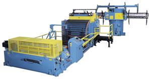
| Figure 2 A combination coil handling system uses one-third the floor space of a conventional system. |
For jobs that require a higher degree of straightening, servo-driven straightener/feeder combination systems with either a motorized stock reel or coil cradle (Figure 2) probably make the most sense. Typically, the combination equipment has entrance and exit feed rolls with a precision straightener mounted between them. The entrance feed rolls can be used to thread the material into the machine. After thread-up, the entrance feed rolls assist the exit feed rolls in accurately positioning the material.
With two sets of feed rolls, the straightener/feeder provides twice as much grip force as setups with a separate servo feed and a pull-through straightener. In some applications not dependent on high-speed processing times, all the straightening rolls in the straightener/feeder may be powered, reducing material slippage and ensuring an accurate part length.
For applications in which heavy material is handled, a cradle/straightener/feeder combination (Figure 3)is usually the machine of choice. These machines allow thick, high-yield material to be supported on the coil's outer diameter, minimizing the risk of losing control of the coil.
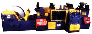 |
| Figure 3 A combination system incorporating a straightener and feeder with a cradle is a suitable choice for thick, high-yield material not destined for a surface-sensitive application. |
These machines are not designed for surface-sensitive material because the coils are supported by large-diameter coil cradle rolls that will mark the material as it starts and stops. They also are not designed for partial-coil operation, as it is not safe to try and reband the coil within the cradle.
Servo feeds with pull-through straighteners and servo-driven straightener/feeder combination systems can be used with progressive tooling. However, they should be fitted with a straightener roll release along with a feed roll release. This allows the pilots to register the material and help ensure acceptable performance while running progressive-die tooling.
Limited space favors the combination coil systems. No looping pits are required, and servo feeds with pull-through straighteners and servo-driven straightener/feeder combination systems typically require approximately one-third the floor space of a conventional line. The cradle/straightener/ feeder combination is the true space manager, requiring approximately half the floor space of a conventional system equipped with an independent servo feed and straightener.
A Conventional Look
 |
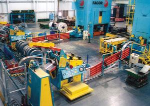
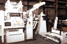
| Figure 4 A conventional coil handling system is more suitable for an application involving surface-sensitive material or progressive-die tooling. |
Combination systems do not compare favorably to conventional systems (Figure 4) when it comes to abrupt stops. When material is stopped between rolls in a combination system, particularly staggered rolls as in a straightener, a series of straight lines is apt to be imprinted across the surface. These imprints are called stop marks, set marks, or even witness marks, the latter being used when the marks show up prominently only after a subsequent process such as painting or plating "bears witness" to them.
In combination systems, the material stops in the straightener with every feed stroke, risking the chance of such marks throughout the coil run. The stop marks will correspond directly to the roll spacing and feed length. Thus, when it comes to surface-sensitive materials or materials destined for an application requiring a critical finish, a conventional system is the preferred equipment.
A conventional servo-feed system, which requires an independent straightener, is ideal for applications involving surface-sensitive material or progressive-die tooling. A powered straightener is an independently driven, freestanding machine, normally controlled with an ultrasonic loop control device that monitors the material in the loop area and regulates the output speed of the straightener accordingly for synchronization with related equipment. Powered straighteners can be adjusted to minimize stopping or be equipped with a "creep" speed for nearly continuous running to prevent witness marks in critical-finish applications.
The top feed roll of the servo feed is easily lifted for pilot pin registration by the press control. This roll lift also allows for proper material tracking by allowing the material to relax every time the rolls are opened.
Conventional systems also offer a lot of flexibility in specialty applications. In zig-zag operations, the material needs room to swing in the looping area as the servo feed shifts laterally with every stroke of the press. In coil-fed or transfer operations, the servo feed can detach from the press and power travel out of the way to allow room to move in a die cart and allow the press to be blank-fed for transfer operations.
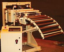
Conventional systems meet the needs of handling high-strength, low-alloy (HSLA) steel as well. In some facilities where HSLA blanks are produced to support transfer operations at other locations, companies are finding out that a straightener works the material only enough to remove coil set as the blanks are cut. As the blanks sit over time, the coil set can reappear within the blanks. For these applications, a conventional coil system supplied with a corrective leveler in place of a straightener can provide the solution. A corrective leveler with 17 or 19 work rolls allows the material to be worked more substantially and produces a part that is free from all material memory. A corrective leveler (Figure 5) also allows for shape correction to reduce or remove edge wave and center buckle coil conditions.
 |
| Figure 5 A corrective leveler can be integrated into a conventional coil handling system to provide parts with a great degree of flatness. |
Conventional coil handling systems do carry higher price tags than combination systems and take up more floor space, but for high-production stamping where versatility and production are priorities, a conventional line with independent servo feed and independent straightener reigns supreme.
A Look at Automation
Automation can be applied to both combination and conventional coil handling systems. The level of automation desired needs to be defined early in the selection process.
At first glance it appears that automation adds cost to the equipment. However, this automation can quickly pay for itself in reduced downtime. Automation levels can range from mild to wild. A "mild" automation system today provides for communication between the coil handling equipment and the press control. A moderate level of automation covers equipment communication requirements as well as push-button controls, system diagnostics, programmable logic control ladder logic, recommended thread-up details, and maintenance information. A "wild" level of automation has not only all the features of the mild and moderate levels, but also complete system setup capabilities. In this "wild" scenario, a coil handling system can completely prepare itself for material thread-up following a simple download of a job order:
- The stock reel-powered backstop sets to the proper material width.
- The brake tension regulates as the coil outside diameter is reduced.
- The straightener head sets up for the material thickness.
- The straightener-powered edge guides set to material width.
- The feed sets up for feed length and speed.
- Powered edge guides set to width.
- The powered cabinet adjusts to required passline height.
With these upper levels of automation, the downtime associated with material thread-up is significantly reduced.
Before investing in coil handling equipment and automation, look hard at your application, floor space requirements, and material specifications. Those answers will help you get a handle on your coil handling decision.
Matthew Watson is national sales manager, FORMTEK Maine, Cooper-Weymouth, Peterson, Rowe, B&K, Coilmate/Dickerman Divisions, 76 Hinckley Road, Clinton, ME 04927, 800-247-2645, ext. 200, www.cwpcoil.com, www.runwithrowe.com.
About the Author
About the Publication
subscribe now

The Fabricator is North America's leading magazine for the metal forming and fabricating industry. The magazine delivers the news, technical articles, and case histories that enable fabricators to do their jobs more efficiently. The Fabricator has served the industry since 1970.
start your free subscription- Stay connected from anywhere

Easily access valuable industry resources now with full access to the digital edition of The Fabricator.

Easily access valuable industry resources now with full access to the digital edition of The Welder.

Easily access valuable industry resources now with full access to the digital edition of The Tube and Pipe Journal.

Easily access valuable industry resources now with full access to the digital edition of The Fabricator en Español.
- Podcasting

In this episode of The Fabricator Podcast, Caleb Chamberlain, co-founder and CEO of OSH Cut, discusses his company’s...


