


Contributing Writer
The maximum operating speed of a stamping operation should be limited, in theory, only by the maximum number of strokes per minute (SPM) that the press can achieve. In reality, production speed is limited by other factors as well. For instance:
 |
1. The uncoiler may not unwind fast enough to keep up with the press.
2. The straightener may be too slow.
3. The feed may not run accurately - - if at all - - at higher speeds.
4. Die and product tolerances can make running at high speeds impossible.
Over the years, a variety of feeds have been used in the stamping industry, each reflecting a period in the history of automatic coil-feed stamping. Early models were the hitch feed and the ratchet-style roll feed. Clutch-driven roll feeds (based on a one-way clutch) and air-driven gripper feeds were widely used until 15 years ago.
The proliferation of high-speed presses since that time has been matched by the growth in the use of cam-driven roll and gripper feeds. The most recent development has been the roll feed, driven by servomotor technology.
During the past couple of years, press feeds have developed at a faster rate than the high-speed presses on which they are mounted. Most of the improvements in press feed speed and usability are attributable to the rapid progress of technology in the areas of cams and microelectronics. These changes are so significant that some users are replacing feeds that were installed only a few years ago - - and that may have been expected to operate for decades - - with newer feeding equipment.
Feed manufacturers are beginning to offer product lines that include 1,000-SPM servo-driven feeds, 2,000-SPM cam-driven roll feeds, and 3,600-SPM cam-driven gripper feeds. Until recently, slower press feeds prevented high-speed presses from reaching their full potential. Today, maximum press speeds - - rather than the top speed of the press feed - - more commonly limit the speed of the operation. Several other considerations limit maximum feeding speeds as well.
Gripper or roll-type feeds operate on the principle of feeding force. This feeding force is the product of the coefficient of friction between the grippers or feed rolls and the material being fed. Feeding force is expressed by the following equation:
F = µG(kgf)
where: F = feeding force
µ = coefficient of friction between material and grippers or feed rolls
G = grip force
kgf = kilogram force
On the other hand, the feeding force required to actually advance material under given conditions (F0) is a kinetic property obtained with the following equation:
F0= mA + CV + kS + (Fx + Fy + Fz)
where: mA = inertia force (kgf)
m = mass of material being fed
A = f"(t) acceleration (velocity differentiated by time (t)) (m/sec2)
CV = viscous force (kgf)
C = viscous resistance (kgf x s/m)
V = f'(t) velocity (feed pitch differentiated by time(t)) (m/sec)
kS = spring force (kgf)
k = spring factor
S = f(t) feed pitch (m)
Fx = initial spring tension (kgf)
Fy = friction force (kgf)
Fz = gravitational force (kgf)
Thus, feeding material under a given set of conditions to a desired tolerance requires that the feeding force exerted on the material always be equal to or greater than F0. If feeding force is less than F0, the feed rolls or grippers will slip on the material, and accurate feeding is impossible.
Reviewing each force as a factor of the feeding equipment or feeding conditions (such as material and equipment layout) will help in evaluating the feeding process.
1. Grip Force. Grip force is inherent to the feed and is usually displayed in terms of the maximum force that a feed can exert. However, because excessively high grip force can mark material, the maximum grip force actually used is typically based on specific feeding conditions.
Material marking is caused by pressure exerted on the surface of the material. By increasing the area of contact between the feed and material, a greater grip force can be exerted without marking the material because the pressure is spread out. This same principle can be applied to a roll feed by increasing the roll diameter or width. This results in a larger contact area and thus a higher grip force value without marking the material.
For a gripper feed, the contact area of the grip jaw determines the maximum grip force value. Because a grip jaw provides a larger area of contact than a feed roll, it exerts lower surface pressure at the point of contact. This is beneficial for feeding soft materials but can complicate matters when feeding materials that require higher grip forces.
2. Factors of Time. Feeds are limited by the dynamic factors of feed length, velocity, and acceleration.
S = f(t), V = f'(t) = df(t)/dt
A = V' = f"(t) = d2f(t)/dt2
where: S = displacement
t = time
d = differentiation by time
Displacement refers to the feed length. Time is determined for a cam-driven feed by the cam's indexing period and the SPM. For a servo-driven feed, it is determined by the time required to advance the material. Velocity and acceleration are obtained from the motion characteristics, either the cam curve or the servo control characteristics. If motion characteristics are defined, velocity and acceleration become functions of time, allowing their values to be calculated for every possible SPM.
To feed at high speeds, minimizing acceleration is the best approach because it limits the amount of stress placed on the feed and reduces the chance of material slippage. For a cam-driven feed, this means that the indexing period should be as close as possible to 360 degrees. For a servo-driven feed, the feeding time should be extended as close as possible to the full press cycle.
Grip force and dynamic factors are the only influences affecting feed speeds that are inherent to the feed. All other factors influencing feed rates pertain to conditions of a specific job. This may suggest that the inherent factors of the feed have only a small effect on high-speed feeding.
3. Coefficient of Friction. The contacting surface material is only one factor that determines the coefficient of friction, which can also vary depending on the condition of the surfaces (shape and roughness) and on the presence of any film between the contacting surfaces. The former usually results from changes caused by surface wear, while the latter is determined by ambient operating conditions, particularly the type and amount of lubricant that is used.
Speed, temperature, and surface pressure also affect friction, but these are minor factors compared to lubrication. If stock must be oiled to lubricate a die, a stamper should consider installing the oiler after the feeder or changing to an oil with a higher coefficient of friction such as mineral or traction oil.
4. Inertia Force. Inertia force is the product of mass and acceleration. During high-speed feeding, inertia force is the greatest load that affects feeding force. Therefore, inertia force must be minimized when feeding at high speeds. Reducing the mass of the material under a given set of conditions requires reducing the length of material that must be moved (see Figure 1), which in turn reduces the inertia force.
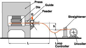 |
| Figure 1: The relationship between the feeder and the material in a press forming operation is demonstrated in this drawing. |
5. Viscous Force. Viscous force is the product of viscous resistance and velocity. It increases proportionally with velocity. If bone-dry guides or bearings/rollers are used, no viscous force exists. However, if the material is oiled, a film develops between the material and the guide, producing viscous resistance.
The amount of viscous resistance is affected by three factors:
1. Oil type
2. Operating temperature
3. Area of contact
To reduce this resistance, the effects of one or more of these factors must be lessened. Corrective measures include using a lower-viscosity oil or cutting grooves along the face of the guides to reduce the contact area. Another alternative is to eliminate viscous resistance altogether by installing miniature roller bearings at all contact points in the guides.
6. Spring Force. Spring force is expressed as the product of a spring constant and feed length. In most applications, this force is minimal, but it often comes into play when feeding thick material or material with relatively large round or square cross sections.
The minimum bending radius of most steels is greater than 500 times the material's thickness. A loop that is less than this bending radius can produce permanent bends in the material, which can affect the flatness of the final product. For example, to feed material 5 millimeters thick, at least 5 X 500, or 5 meters, of material must be maintained between the straightener and the feed.
Because factory floor space is precious, a method is needed to maintain a large curvature radius in the material loop without requiring much room between the feed and straightener. The resulting loop contour resembles a bow, which, when material is being fed, generates spring force in the feeding direction.
Pushing material in the feeding direction produces a stronger feeding force at the end than at the beginning of the feed cycle. If the feed has a low grip force, the material could slip at the end of the feeding cycle, causing a longer feed pitch than is desired. Replacing the feed with one having higher grip force is one option. Another alternative is adding material guides to create more resistance in the feeding direction.
7. Initial Spring Tension. Once the feeding conditions have been established, parameters representing initial spring tension, friction force, and gravitational force are substituted as constants or initial values into the equation for calculating the force required to feed material (F0). Feed motion has no effect on these constants.
The initial spring tension (Fx) is determined by the amount of strain acting on the spring factor of the material. This relationship is expressed as:
Fx = K0X S0
where: K0= spring factor
S0= strain
Initial spring tension occurs when a loop controller or similar device tries to bend coiled material. Initial spring tension is closely related to spring force in that the nature of the force applied by a loop controller, straightener, or uncoiler can also affect initial spring tension.
When feeding at high speeds, initial spring tension and spring force play important roles that, in conjunction with straighteners and loop controllers, may hold the key to successful high-speed feeding.
8. Friction Force. As mentioned earlier, a feed's potential feeding force is a product of grip force and coefficient of friction. This is similar to friction force except that friction is treated as a load, and it occurs mainly at the material guides and within the die. With the press at the top of the stroke and the feed open, friction force can be measured simply by pushing or pulling on the material with a spring balancer. Obviously, the smaller this parameter, the better.
Friction force under static conditions may differ from that which exists when a press is running. One reason for this is the intense amount of stress that can occur between the feed and the material guides when the material skews. This stress becomes a friction load and is most apt to occur when material is fed continuously with two feed rolls.
Feeds that use two rolls are prone to skewing problems when the cross section of the material is tapered. This stress can be relieved by a release mechanism that opens both rolls at the end of each feed cycle or by an automatic aligning mechanism in one of the rolls.
Some gripper and roll feeds use an oscillating motion to advance the material. The mechanism of these feeds is divided into a feeding section and a stationary section. The feeding section contacts the material during the feeding cycle and releases during dwell. During dwell, the stationary section firmly grips the material.
This design automatically releases residual (horizontal) stress between the feed and the material. As a result, feeds of this design can feed continuously (when no release is used, such as with pilotless dies) with very little friction force.
Friction force can also occur in massive proportions when material deflects or buckles while being fed at high speeds. Deflection most often occurs between the guide on the push side of the feed and the die. For this reason, careful consideration should be given to the material guide placed between the die and the feed's point of contact. Feeding soft materials at high speeds can often be assisted by using a pull feed or a push feed and pull feed together.
9. Gravitational Force. Gravitational force is the cumulative total of the difference of elevation with respect to ground level, material dimensions, and the material's specific gravity. The gravitational load is smaller than the inertia load and is not a major concern.
Force exerted during each feed cycle generates vibration in the material that can eventually create a bumping effect. In contrast, material advancing from an uncoiler through a straightener progresses at a constant speed, producing a steady flow of material. A loop controller placed between the intermittent motion of the feed and the continuous motion of a straightener acts as a damper.
Loop controllers can be used with free-hanging loops or S-loops, depending on the application. However, when the strokes per minute increase, the loop controller is incapable of preventing the material from bumping, often so much so that the system cannot be used at the higher speed ranges.
One option for addressing this problem is a system in which material progression is determined directly by the feed pitch and the SPMs. This data is fed into a microcomputer which controls the servomotor that drives the feed rolls in the system, advancing the material continuously. Sensors control the speed of the material so that the loop stays within a certain range (see Figure 2).
 |
| Figure 2: Loop controllers can be used with free-hanging loops or S-loops. Sensors control the speed of the material to keep the loop within given range. |
The proliferation of high-speed feeds has been made possible by automating the adjustments of feed pitch, material thickness, grip force, material width, and pass line. Because of this, products of varying specifications can be made on the same equipment.
As this article illustrates, many factors may hinder successful high-speed feeding. Some of them can have a major impact on the speed with which a given die can run. For the most part, potential problems in high-speed feeding can be remedied. However, if the problem cannot be pinpointed, it is best to start with the basic principles of feeding. These principles should allow feeding throughout a desired speed range without marking the material, without feed pitch error, and without introducing camber.


The Fabricator is North America's leading magazine for the metal forming and fabricating industry. The magazine delivers the news, technical articles, and case histories that enable fabricators to do their jobs more efficiently. The Fabricator has served the industry since 1970.
start your free subscription
Easily access valuable industry resources now with full access to the digital edition of The Fabricator.

Easily access valuable industry resources now with full access to the digital edition of The Welder.

Easily access valuable industry resources now with full access to the digital edition of The Tube and Pipe Journal.

Easily access valuable industry resources now with full access to the digital edition of The Fabricator en Español.
In this podcast episode, Brian Steel, CEO of Cadrex Manufacturing, discusses the challenges of acquiring, merging, and integrating...


