


Professor Emeritus and Director - Center for Precision Forming

Editor's Note: This article is Part III of a three-part series discussing finite element (FE) simulation for tool and process design in hot-stamping boron steel. Part I, which appeared in the December 2006 issue, discussed the types and applications of the hot-stamping process. Part II, which appeared in January 2007, discussed the microstructure of boron steels and coatings on the sheet surface.
This column was prepared by the staff of the Center for Precision Forming (CPF, formerly ERC for Net Shape Manufacturing), The Ohio State University, Taylan Altan, professor and director.
Hot stamping comprises a forming process and then cooling the formed part within the die. Finite element (FE) simulation of hot stamping is currently under development. To model the hot-stamping process accurately, FE simulation needs to predict the mechanical, thermal, and microstructural changes in the workpiece (see Figure 1).
Material data is needed over a range of forming temperatures (600 degrees C to 900 degrees C) and deformation rates to conduct reliable process simulations. Changing surface conditions during forming (such as formed scale on the sheet surface) significantly influence heat transfer as well as friction between the workpiece and tool.
Because forming a heated workpiece occurs quickly (forming speeds are approximately 500 mm per second), a simplified isothermal analysis could be made assuming no temperature changes occur during actual deformation. However, workpiece cooling in the die must be considered assuming that nearly all the cooling occurs after the part is hot-formed.
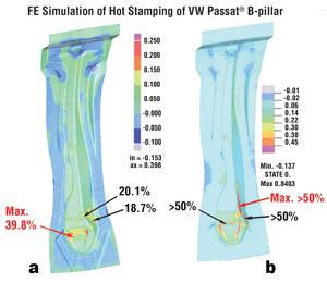
Figure 2a shows results from an isothermal hot-forming FE simulation of a B-pillar. In an isothermal analysis, a single flow stress curve and friction coefficient are input to figure the finite element method (FEM). Temperature and the effect of forming speed are not accounted for.
Figure 2b shows results for a thermomechanical FE simulation. This FE simulation considers the temperature gradients within the material, as well as the effect of forming speed and heat transfer between the tools and the workpiece.
Microstructural changes, such as transformation to martensite, are not considered in this analysis. Research in predicting and modeling microstructural changes in a workpiece using FEM is in progress. 2
After the forming process is completed, the part must be cooled as quickly and homogeneously as possible. As discussed in the December 2006 issue, the hot-formed part is quenched within a closed die at a cooling rate of approximately 50 degrees C to 100 degrees C per second.
Tool design is particularly critical during the cooling process. The die must absorb and dissipate a significant amount of heat energy through integrated cooling channels. Cooling channels should be designed to achieve a homogeneous distribution of mechanical properties in the formed part.
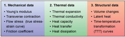
Figure 1: The challenge in FE simulation is developing a material model that can accurately account for the interaction of the mechanical, thermal, and microstructural data.1
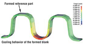
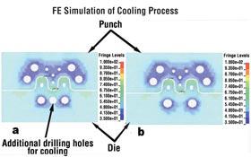
Thermal FE analysis can assist tool designers in estimating temperature distribution within a workpiece and tool. Figure 3a and Figure 3b show the temperature distribution for two tools with different cooling channel designs. The die shown in Figure 3a has an additional drilling hole. A comparison of temperature distribution between two cooling designs shows that cooling capacity is improved by drilling an additional hole. Figure 3c illustrates a formed part's temperature distribution.
An insufficient cooling rate because of poor tool design can be predicted and corrected using FE simulation. Besides temperature distribution, thermal FE analysis also can be used to predict the cycle time required to cool a part to approximately 150 degrees C. At this temperature, a part can be safely withdrawn from the die. Thus, a controlled and optimized hot-stamping process can be developed with FE analysis. 3
Until now most of the research related to FE simulation of hot stamping has been done in Europe. However, the Center for Precision Forming (formerly ERC/NSM) also is conducting warm-forming simulations. The CPF also has extensive experience in the simulation and modeling of hot- and warm-forging processes, which are similar to hot stamping.
Taylan Altan is a professor and director of the Center for Precision Forming (formerly Engineering Research Center for Net Shape Manufacturing), 339 Baker Systems, 1971 Neil Ave., Columbus, OH 43210-1271, 614-292-9267, www.cpforming.org. The CPF conducts research and development; educates students; and organizes workshops, tutorials, and conferences for the industry in stamping, tube hydroforming, forging, and machining.

Professor Emeritus and Director - Center for Precision Forming


The Fabricator is North America's leading magazine for the metal forming and fabricating industry. The magazine delivers the news, technical articles, and case histories that enable fabricators to do their jobs more efficiently. The Fabricator has served the industry since 1970.
start your free subscription
Easily access valuable industry resources now with full access to the digital edition of The Fabricator.

Easily access valuable industry resources now with full access to the digital edition of The Welder.

Easily access valuable industry resources now with full access to the digital edition of The Tube and Pipe Journal.

Easily access valuable industry resources now with full access to the digital edition of The Fabricator en Español.
In this episode of The Fabricator Podcast, Caleb Chamberlain, co-founder and CEO of OSH Cut, discusses his company’s...


