


How link motion affects blanking, feeding, and inertia on mechanical presses
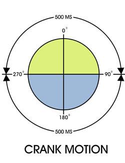 |
| Figure 1: Timing Chart for Crank Motion Press, 60 SPM With a crank motion drive, the crank rotation from 270 to 90 degrees (top half of the press stroke) takes 500 milliseconds, the same amount of time it takes for the crank to rotate from 90 to 270 degrees (bottom half of the press stroke). |
To improve metal flow, stamping press builders in recent years have designed drive modifications that alter the press's slide motion as it goes through the working portion of the stroke. These modifications include draw link, progressive die link, vertical link, and knuckle joint motions.
Progressive die and vertical link motions are suitable for heavy blanking operations. Because these two link motions reduce slide velocity in the working portion of the press stroke, shock and vibration can be reduced by 30 percent to 70 percent compared to normal blanking operations, depending on the velocity reduction. This reduction in shock and vibration in turn reduces the noise level and reduces wear and tear on the press and auxiliary equipment attached to it.
The reduced shock and vibration also nearly eliminate nuisance failures, such as related guards shaking loose, wiring in press controls coming loose at the terminal points, and fatigue cracks developing in sheet metal components.
Feeds or Transfers Applied to Link Motion Presses
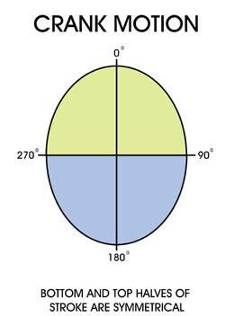 |
| Figure 2: Timing Chart for Link Motion Drive, 60 SPM. With link motion, because the slide velocity is reduced through the working portion of the press stroke, more time is consumed there. To maintain the press cycle rate, the velocity is increased as the slide travels through the top portion of the press stroke. |
Using feeds or transfers on modified slide motion presses requires an understanding of the reduced time available in the upper portion of the slide stroke. Traditionally, feed timing has been based on degrees of crankshaft rotation. On link motion presses, however, the slide velocity is increased through the upper portion of the press stroke, so there is less time available to complete the feed cycle.
Figure 1 is a timing chart for a standard crank motion press operating at 60 strokes per minute (SPM). With a crank motion drive, the crank rotation from 270 to 90 degrees (top half of the press stroke) takes 500 milliseconds, the same amount of time it takes for the crank to rotate from 90 to 270 degrees (bottom half of the press stroke).
In comparison, Figure 2 is a timing chart for a typical link motion drive operating at 60 SPM. Because the slide velocity is reduced through the working portion of the press stroke, more time is consumed there. To maintain the press cycle rate, the velocity is increased as the slide travels through the top portion of the press stroke. In this illustration, the bottom one-third of the press stroke consumes 50 percent of the cycle time, while the remaining two-thirds consumes the remaining 50 percent of the cycle time. Feed systems are activated in this upper two-thirds of the stroke, but the time available to move material through the die space is reduced.
With servo-driven feeds or transfers, users no longer should set the feed cycle using degrees of crankshaft rotation. Instead, they must compare the number of milliseconds to complete material feeding with the press timing diagram. From a practical perspective, using milliseconds to determine the feed cycle is no more difficult than using degrees of crankshaft rotation; it just requires a different set of timing diagrams.
Mechanical press feed systems that are driven from a power takeoff on the crankshaft accelerate faster with a link motion drive than with standard crank motion. However, this increased acceleration may require the press speed to be reduced.
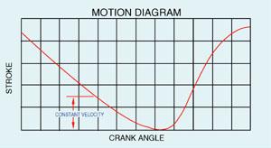 |
| Figure 3: Constant Velocity of Draw Link Motion. Draw link motion helps maintain constant slide velocity while the drawing operation is performed, which helps reduce side-wall thinning. This constant velocity is illustrated in this graph by the straight portion of the velocity curve. |
Dynamic Balancing of Inertia Forces
Inertia forces in a press are the result of a mass (the slide and upper die) moving at a certain velocity. The reciprocating motion of the press slide and the upper die creates an inertia force that alternately tends to lift the press (the upstroke) or push it toward the floor (the downstroke).
The increased slide velocity during the upstroke on a link motion press generates higher lifting forces, especially on progressive die presses that can have cycle rates higher than 100 SPM. In these high-speed presses with link motion drives, the inertia forces can affect the stability and performance of the press and die system.
To prevent the negative effects of this inertia, presses with link motion drives incorporate a dynamic balancing method. Two large weights at the ends of the press crankshaft act in the opposite direction of the slide and upper die, which cancels the inertia. With the dynamic balancing system, the floor and press mounting systems experience only the static weight of the press and die.
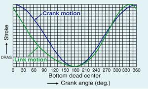 |
| Figure 4: Progressive Die Link Motion Versus Crank Motion. This graph illustrates the reduced slide velocity of a progressive die link compared to a standard crank motion. To reclaim the lost time created by the slide velocity reduction in the lower portion of the press stroke, the velocity is increased through the upper portion of the stroke so that strokes per minute are not sacrificed. |
Link Motion and Spring-loaded Strippers
Because progressive die and vertical link motions reduce slide velocity through the working portion of the press stroke, the velocity must be increased through the upper part of the press stroke to reclaim the time lost so that cycle rates can be maintained. If this increased velocity were to begin immediately after the slide passed through the bottom of the press stroke, the spring-loaded stripper velocity also would increase, which could have a negative effect on the stripper bolts. This would be the case if a draw link motion drive were used for progressive die operations.
Figure 3 shows that the slide velocity increase starts immediately after the bottom of the press stroke with a draw link. However, Figure 4 and Figure 5 show that the progressive die link and vertical link motions do not increase slide velocity until the stripper has lifted off of the material. In fact these two motions actually reduce the stripper velocity when compared to standard crank motion. Therefore, the load on the stripper bolts actually is reduced.
 |
| Figure 5 Vertical Link Motion. Vertical link motion is a modified slide motion that more than doubles the time that the punch is engaged with the metal being formed. This flow control forming process forces the metal to flow plastically under the pressure provided by the press and produces parts with the metal redistributed to desired areas. |
Dennis J. Boerger is national sales manager with AIDA-Dayton Technologies Corporation, 7660 Center Point 70 Boulevard, Dayton, OH 45424-6380, phone 937-237-2382, fax 937-237-1995, Web site www.aida-america.com. For more than 80 years, AIDA has been a global builder of metal forming and stamping presses, as well as nontraditional technology. See the January/February 2002 issue of STAMPING Journal for the first installment of this article.
About the Publication

subscribe now

The Fabricator is North America's leading magazine for the metal forming and fabricating industry. The magazine delivers the news, technical articles, and case histories that enable fabricators to do their jobs more efficiently. The Fabricator has served the industry since 1970.
start your free subscription- Stay connected from anywhere

Easily access valuable industry resources now with full access to the digital edition of The Fabricator.

Easily access valuable industry resources now with full access to the digital edition of The Welder.

Easily access valuable industry resources now with full access to the digital edition of The Tube and Pipe Journal.

Easily access valuable industry resources now with full access to the digital edition of The Fabricator en Español.
- Podcasting

In this episode of The Fabricator Podcast, Caleb Chamberlain, co-founder and CEO of OSH Cut, discusses his company’s...


