


How to draw round cups deeper
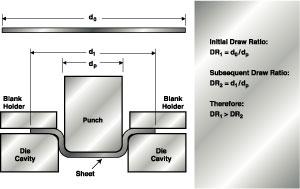 |
| Figure 1: In deep drawing, sheet metal is forced into a die by a punch to form a part. The draw ratio decreases throughout the process. |
In general, deep drawing (see Figure 1) is a process in which a blank is forced into or through a die by a punch to form a hollow component that has essentially the same thickness as the original material. The most critical region of a deep drawn cup is the flange because of the circumferential stresses that occur there.
To prevent wrinkling and to control the process, a blank holder is used as shown in Figure 1. The blank holder's main function is to apply blank holder pressure (BHP) to the cup flange to suppress wrinkling. If no blank holder is used or insufficient blank holder force (BHF) is applied, the cup may wrinkle as shown in Figures 2c and 2d.
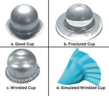 |
| Figure 2: Properly performed, deep drawing can produce a cup such as that shown in (a). However, improper blank holder force can cause fracture (b) or wrinkling (c). The process can also be computer modeled (d). |
A secondary function of a blank holder is to restrain material flow into the die by increasing friction at the flange. This increased friction causes increased radial tension that must be supported by the cup wall. If too much BHF is applied, fracture may result before the desired cup height is attained (see Figure 2b). Only with properly applied BHF can a good cup be drawn (see Figure 2a).
Draw depth is therefore limited by the onset of wrinkling and fracture. These limits are depicted in Figure 3. In this chart, BHF is plotted along the horizontal axis, and the draw depth of the cup is shown along the vertical axis. If the BHF is too low, the draw depth is restricted by the limits of wrinkling. If the BHF is too high, the draw depth is limited by fracture. These lines intersect at the maximum possible draw depth.
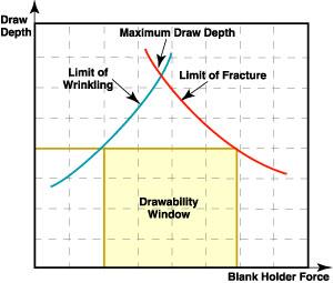 |
| Figure 3: The intersection of the lines plotting the BHF and the draw depth of a cup reveal the maximum possible draw depth for a given cup. |
Varying the BHF
Often, a constant BHF is applied throughout the forming stroke, even though the drawing ratio decreases as the flange is drawn in, as shown in Figure 1.
Time-variable BHF currently is used in industrial stamping processes, although not typically in an optimal fashion. In double-action mechanical presses, BHF is applied with a position setting of the outer ram. Typically, the BHF is not known unless a load sensor is installed, but it tends to vary with the action of the mechanical linkage.
In air or nitrogen cushions, the BHF typically increases with ram stroke as a result of the gas compression. In a hydraulic cushion, BHF is typically constant throughout the ram stroke. Neither of these BHF profiles is desirable, because they do not vary optimally in time.
To control BHF, modern presses can be equipped with NC hydraulic cushions, which can vary BHF throughout the stroke of a press. Older presses may be retrofitted with NC hydraulic cushions as well.
Further Research
Much research has been conducted into varying BHF as a function of press stroke. One control strategy that has produced improved results is varying the BHF from its fracture limit to its wrinkling limit.1This is an empirical method and requires extensive experimentation to determine the proper BHF trajectory.
Analytical methods are becoming available to predict optimal variations of the BHF for round cups. This equation was proposed for predicting an appropriate level for the BHF that prevents wrinkling2:
 |
| Figure 4:The intersection of the lines plotting the BHF and the draw depth of a cup reveal the maximum possible draw depth for a given cup. |
where: pb = blank holder pressure
c = an empirical factor ranging from 2 to 3
DR = draw ratio (blank diameter/punch diameter)
d0= blank diameter
t0= initial blank thickness
Su= ultimate tensile strength
Because the draw ratio constantly changes through the deep drawing process, this equation can be used to predict an optimal BHF trajectory, as shown in Figure 4. The BHF decreases as expected during the process until the very end, when BHF is increased to ensure proper strain hardening of the final part.
 |
By optimizing BHF variation as a function of punch stroke, researchers have documented dramatic increases in LDRs, including, for example, an increase from 2.1 to 2.6.3
References1. Kazunari Kirii et al., "Binding Force Control of Uni-Pressure Cushion in Automobile Panel Stamping," SAE Technical Papers, No. 950916, 1995.
2. E. Siebel and H. Beisswanger, Deep Drawing (Munich: Carl Hanser Verlag, 1955).
3. Richard Kergen and Philippe Jodogne, "Computerized Control of the Blankholder Pressure on Deep Drawing Presses," SAE Technical Papers, No. 920433, 1992.
About the Publication

subscribe now

The Fabricator is North America's leading magazine for the metal forming and fabricating industry. The magazine delivers the news, technical articles, and case histories that enable fabricators to do their jobs more efficiently. The Fabricator has served the industry since 1970.
start your free subscription- Stay connected from anywhere

Easily access valuable industry resources now with full access to the digital edition of The Fabricator.

Easily access valuable industry resources now with full access to the digital edition of The Welder.

Easily access valuable industry resources now with full access to the digital edition of The Tube and Pipe Journal.

Easily access valuable industry resources now with full access to the digital edition of The Fabricator en Español.
- Podcasting

In this podcast episode, Brian Steel, CEO of Cadrex Manufacturing, discusses the challenges of acquiring, merging, and integrating...


