


Implementing a coil-end joiner
Automotive stamper reduces downtime on its heavy-gauge lines
Almost all metal stampers have downtime at the end of a steel coil. The amount of time a line is nonproductive between coils can vary. It's not uncommon for downtime to exceed 20 minutes. On heavy-gauge lines, where a coil's linear footage is low, the amount of downtime can be excessive.
Pax Machine Works, Celina, Ohio, produces products that are drawn, deep-drawn, blanked, pierced, coined, extruded, and embossed. Its finished parts are sold to OEMs and aftermarket parts suppliers. The stamper runs high-strength steels from 0.090 to 0.140 inch thick with widths of 7 to 11 in., although the line's coil-end joiner can handle material from 2 to 20 in. wide and 0.030 to 0.156 in. thick.
Down on Downtime
To eliminate press rethreading, Pax implemented a coil-end joiner to increase parts per hour, reduce scrap, and minimize manual material handling during coil changes. In a typical line without a coil-end joiner, the coil tail-out and new coil threading procedure involves significant manual intervention that increases downtime and scrap.
In many cases, the coil tail-out must be threaded slowly and manually to make sure the die isn't damaged by misfed parts or abnormalities associated with a coil's end. In addition, a coil's lead end also must be fed manually to make sure no die damage occurs from misfeeds during the changeover process.
Coil-end joiners use gas tungsten arc welding (GTAW), gas metal arc welding (GMAW), plasma, or laser welding depending on the line's specifications. Pax's heavy-gauge line uses GTAW to reduce buildup associated with the weld joint and to eliminate any concerns related to the weld's hardness in relation to the stamping tooling. In some applications, pull tests, bend tests, and hardness tests are required to ensure a weld meets a line's requirements.
"Any process that enables us to manufacture parts with higher productivity and quality at lower cost gives us a competitive advantage," said Joe Hamberg, Pax's plant engineering manager. "The coil welder has been integral in reducing costs (lower scrap rate), as well as increasing productivity (less downtime during coil changes), which allows us to be more competitive when quoting new jobs."
Potential for Die Damage Reduced
The stamper was concerned about the potential for die damage from the welded joint. Excessive material hardness or thickness can damage press guides or tooling. If the weld is too thick, has burnouts on the end of the joint, or if the welded material is not perfectly straight (the lead end lined up with the tail), damage can occur to a press's edge guides or jam in the die.
If a weld is too thick, material buildup also can damage the die or punch. These concerns were eliminated for Pax when GTAW proved to be identical to the parent material's physical properties. As a result, Pax has not experienced any die-related problems from the coil-joining process.
Coil joining is used on stamping lines around the world. In most cases, the weld won't negatively affect the die. For high-carbon applications (higher than 0.2 percent), it may be necessary to anneal a weld's heat-affected zone to prevent hardness buildup.
On noncarbon steels or coated materials, other welding processes can be used in a processing line. It may be necessary to weld with different shielding gases, gas backup bars, water-cooled torches, or other ancillary devices to make sure the weld properties and postweld are as close as possible to the parent metal's properties.
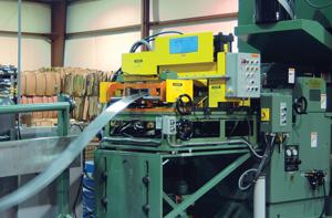
Figure 1The tail-end strip is depleted from the uncoiler and stopped just outside of the coil-end welder by an end detector usually mounted before the straightener. The end detector informs the end welder to begin the tail-out sequence. The strip is positioned as shown in Figure 1.
Safer Coil Changes
Tail-end feeding through the press and rethreading the lead end often are done over a loop pit, although this is not the case at Pax. This type of operation poses significant safety risks, such as falling, handling razor-sharp material, getting parts in and out of the die, and feeding the lead end into the feed at the end of a pit.
The stamper eliminated cutting up and removing parts during the tail-out sequence, which improved ergonomics and operator safety. The operator no longer has to pull material out of the press or cut material in the tool, which saves time and makes the process less physically demanding. In some cases, a coil joiner also can be used to weld one production size to the next scheduled run to eliminate rethreading that usually accompanies a product changeover.
"Before installing the welding machines, jobs with longer dies and heavy-gauge material were difficult because we had to break the strip up into smaller sections to remove it from the tool before stringing up the next coil," said Hamberg. "After adding the welding machines, most body motions were eliminated."
Less Scrap
The amount of scrap produced varies with a part's length, coil lead and tail-end quality, the complexity of the part, and its tolerance. Pax was able to reduce its scrap around the weld location during the tail-end and lead-end rethreading process.
Savings are realized from reduced scrap at the end of coils and the beginning of new coils, including scrap generated from losing the setup and retesting parts to be in conformance to the specification. On some strict-tolerance applications, almost all parts at the end of the coil or the beginning of a new coil must be inspected to ensure they are in tolerance before the line can run at full speed.
After adding a coil-end joiner, Pax said it increased its productivity approximately 33 percent, reduced its scrap, and created a safer working environment.
As the tail-end sequence begins, the exit pinch roll closes and the operator jogs the tail-end strip into the coil-end welder for the tail scrap cut. On automated lines, pinch roll jogging automatically occurs, and a second end detector stops the material in the shear position. The shear is activated by the operator (or automatically if light curtain protection is added) to crop the tail-end scrap and drop it through the machine's bottom. Some job shops add a scrap cart under the welder for easy removal of the pieces. The scrap cut removes approximately 10 to 15 inches of strip. Figure 2shows the machine at the end of this cycle.
This entire sequence takes about 40 seconds from the time the welder is given the signal from the flattener. It's assumed that the flattener will have enough control of the material to locate it within 1 meter of entry to the coil-end welder. If this sequence is automated, the operator can begin the lead-end sequence.
The lead-end sequence immediately starts after the operator positions the strip properly on top of the tail-end strip. The operator engages the camber compensation system, if required, to center the lead- and tail-end strip edges. Once the strip is located on-center, the operator activates the shear and crops the lead end (see Figure 3).
Scrap is removed by the operator. The shear and weld station then indexes to the weld position (see Figure 4). Weld clamps are activated, and the operator jogs the torch to the beginning of the strip. On an automated welding machine, the weld-start positioning is automatic, and the end detector automatically begins the weld process. Similarly, the weld is stopped at the end of the cycle automatically. This entire sequence takes approximately 60 seconds
Figure 2
The GTAW process in this application takes between 45 and 100 seconds, depending on strip thickness and width. In general, torch speed of 10 inches per minute (IPM) can be expected. The speed of the weld process is affected by many variables. For wide applications more than 28 in., two torches can cut weld time in half.
| Sequence 1 - Tail End | 40 sec. |
| Sequence 2 - Lead End | 60 sec. |
| Sequence 3 | 30-150 sec. |
| Total Machine Cycle— Welding | 130-250 sec. |
This time cycle chart does not include the operator's time between the identified processes. Total time depends on operator skill. In this case, it's about 10 minutes
Further automation can reduce cycle time. Automating the tail-out sequence, including shearing of the tail end, can reduce overall cycle time, as can automated torch start and scrap discharge.
About the Publication

subscribe now

The Fabricator is North America's leading magazine for the metal forming and fabricating industry. The magazine delivers the news, technical articles, and case histories that enable fabricators to do their jobs more efficiently. The Fabricator has served the industry since 1970.
start your free subscription- Stay connected from anywhere

Easily access valuable industry resources now with full access to the digital edition of The Fabricator.

Easily access valuable industry resources now with full access to the digital edition of The Welder.

Easily access valuable industry resources now with full access to the digital edition of The Tube and Pipe Journal.

Easily access valuable industry resources now with full access to the digital edition of The Fabricator en Español.
- Podcasting

In this episode of The Fabricator Podcast, Caleb Chamberlain, co-founder and CEO of OSH Cut, discusses his company’s...


