


Contributing Writer
 |
| Figure 1A: Traditionally, pins and heel blocks have been located as far outboard as possible. Figure 1B: Different locations can be used, depending on the application. |
Critical path planning and project management time lines influence most projects, including transfer systems and tooling, by causing them to be scheduled on the basis of lead-time. The long lead-time items, such as the press, transfer system, die design, and die build, are started early in the project's life. Shorter lead-time items, such as finger tooling, usually are started long after the die design is well under way, and often when it is completed.
Planning the tooling so late can result in the need for a redesign, which carries with it several problems: Designers may be reluctant to make changes, the redesign could exceed the time and funds budgeted for the project, and critical tryout or pilot production runs for the customer may have to be canceled because of time constraints.
To prevent these problems and to ensure the best performance of the transfer system, the tooling supplier should meet with the die designer at the beginning of the project. Working together as a team, they can generate many no-cost ideas that will increase the speed of the system. An increase of just a few strokes per minute can substantially increase the operation's profitability and return on investment.A meeting with the customer, die designer, and tooling supplier should include a discussion of the press type, transfer type, part weight and size, process sequence, part gripping at each station, method of loading the first die, changeover frequency, and the dropoff method for the finished part.
Before the tooling design work begins, the following die construction principles should be considered to improve the performance of the system:
1. Guide pin or heel block locations. Traditional die design principles suggest that the pins or heel blocks be located as far outboard as possible (see Figure 1A). This allows for the longest lever arm between the contact points to keep the upper die parallel with the lower die during operations. This works well with progressive dies, which have all the motion inside the die, or with line dies, which allow the operator to work between the die pins.
With most transfer systems, this front-to-back location results in a longer clamp stroke, because the fingers' return path is outside the pins, and thus a slower transfer speed results. Figure 1B shows the preferred locations.
Left-to-right pin locations usually are dictated by part size and thus die size. Efforts typically are made to orient the part with its minimum dimension in the left-to-right direction (direction of flow) to get the required number of stations in the press and to maintain a minimal stroke distance. If the press is large and the parts are small, the dies may have to be oriented close together in the center of the press (with the loading system if feasible), or idle stations may need to be added to keep the stroke short.
 |
| Figure 2A: If pins or heel blocks are long, less time is available for the operation. Figure 2B: With shorter pins or heel blocks, there is more time for the transfer motion to occur. |
2. Guide pin and heel block heights. Most stampers know that the pins or heel block posts should be in the upper die shoe, and the bushings or heel blocks should be in the lower shoe. However, the height of the bushings or heel blocks and the length of the pins often are ignored. While this is not a problem with progressive or line dies, a transfer die requires short pins and heel blocks so that the fingers can move as soon as the die begins to open. If the pins or heel blocks are long (see Figure 2A), the system must wait longer for a clear path, so less overall time is available for the transfer operation. When the fingers must move faster, part control often is lost; if the press is slowed down, productivity suffers.
If the pins or heel blocks are shorter on the top and taller on the bottom die, and the engagement point is located near the passline of the transfer, the clear path occurs earlier (see Figure 2B). This allows more time for the transfer motion to occur and allows faster press operations.
3. Stop block locations and height. These are similar to the pin or heel blocks and should be considered in the transfer die design.
4. Lower die profile. Rather than run the movement of the transfer with square corners at the transition of the lift motion and the stroke motion, most servo transfers can round the corner (have an overlap between the two motions). This is possible if there is no interference between the fingers or the lower surface of the part and the lower die construction. More clearance allows more overlap, which creates a larger radius and makes the transition from lift to stroke smoother and faster, increasing potential output.
 |
| Figure 3: In some situations it is better to use a lower cam driver to keep the clear point as low as possible. |
5. Location of cam drivers. One advantage of a transfer is that the part can be rotated to allow perpendicular entry of the punch into the part. However, in some cases, such as on the ends of the part 90 degrees from the part flow, rotation does not solve the problem, and cams must be used for piercing. In such situations, it usually is better to use a lower cam driver to keep the clear point as low as possible (see Figure 3). The upper cam driver causes an obstacle similar to an upper pin that is too long.
All of these suggestions save time by reducing the travel distance of the fingers, starting the motion of the transfer early in the cycle, or rounding the corners of various motions. At a fixed press speed, these improvements slow the finger motion and reduce the chance that part control will be lost.
 |
| Figure 4: A station that loads blanks outside the ram should be avoided unless the parts are small enough in relation to the press and the distance between columns. |
Several problems can occur in a transfer application:
1. Clearance between columns. If a press is filled with numerous or large dies, stampers sometimes ask transfer or tooling builders to provide a station to load blanks outside the ram, between the press columns. This seems like a good solution to the space problem, but it can cause the loading station to run out of room, even if the fingers are shortened as much as possible. This condition should be avoided unless the parts are small enough in relation to the press and the distance between columns (see Figure 4).
2. Insufficient clearance for gripper jaws. Die designs often do not provide sufficient clearance for gripper jaws; as a result, adjustments become critical or additional clearance must be ground in the dies after the build. Extra clearance of 1 inch in the vertical direction and 1/2 inch in the horizontal direction should be provided in the initial die design (see Figure 5).
 |
| Figure 5: Extra clearance should be provided in the initial die design. |
3. Blank sag. If the blank is long and the material is thin, blanks cannot be loaded with just shovels because of excessive blank sag. Grippers can be used to pull outwardly on the blanks to minimize the problem, but sometimes the die will require a fixed or a movable up and down support to get the blank into the draw station (see Figure 6).
4. Lack of pickup point. One clever method for locating a good point for a shaped finger tool to pick up a part is to use a thumbnail. This is particularly helpful in a draw station where metal flow is present and the outer edge of the blank can vary in position depending on metal thickness and properties. The thumbnail is generated by forming a bump in the outer area of the blank just as the draw is completed.
 |
| Figure 6: The die may need a fixed or movable support to get the blank to the draw station. |
While most transfer system manufacturers start out with dedicated, one-of-a-kind tooling that uses shims or slots for adjustment, the amount of adjustment that can be achieved may not be enough for some applications.
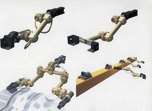
Modular tooling (seeFigure 7) is another alternative that can offer increased flexibility. Typical components include a solid-aluminum base with four holes for mounting, swivel assemblies to provide independent rotation, tooling arms made of drawn aluminum tubing, shovels of various sizes and designs, edge-sensing assemblies for detecting part presence without sensor damage, swivel and solid gripper mounting brackets, an internal wedge for mounting shovels and crossbars, tooling links for close right-angle tubing situations, and reducing links for tubing size reductions.
With lightweight, modular tooling, individual adjustments can be made one axis at a time without affecting the other adjustments. Its strength and rigidity help prevent sag with heavy loads and retain settings throughout the run. Unlike hard-tooled fingers, this type of finger tooling can be rebuilt or replaced in minutes. It also can be reused for future jobs.
 |
| Figure 7: Modular tooling is an alternative that can increase flexibility. |
End effectors are the connection between the finger tooling and the part that is in the die. Various types of end effectors are used, depending on the attitude of the part during processing, the type of material, the shape of the part, and the surface finish requirements. End effectors can be shovels of various types, special-shaped shovels, vacuum cups, magnets, or grippers.
Shovels. Shovels often are the first alternative considered because of their simplicity and durability. With no moving parts, they can be used to trap and support the part for controlled transfer to the next station. This is particularly true with heavy materials or those that do not sag or bend. Shovels come in a variety of sizes and are made from sheet metal or cast steel.
Special Shovels. Many standard shovels can be modified to satisfy unusual or specific shapes. Often the shovel is shaped like the part contour to provide more complete support in all axes. One version traps the part with the upper and lower fingers, while another engages the thumbnail until the trim operation cuts off the excess material.
Vacuum Cups. Vacuum cups can be used to prevent surface blemishes. Air-powered venturi units mounted with the cups provide the vacuum, while a secondary blowoff feature releases the part. Vacuum cups work well on surfaces that are horizontal or almost horizontal, but they often slide on more vertical parts. Also, if the surface is too small, is uneven, or has holes or louvers, the vacuum cannot generate in the cup to hold the part.
Magnets. A new style of magnets uses high-power permanent rare-earth elements and air-powered retraction to move parts from station to station. They come in several sizes: Lightweight models generate carrying forces from 10 to 35 pounds, while heavier varieties can lift as much as 100 pounds. They usually work best on vertical or nearly vertical surfaces.
Grippers. Air-operated grippers, sometimes called clamps, come in a variety of designs. While they can be the most expensive end effector option, they typically are required to grip a thin blank to reduce sag or to ensure proper location in the first die. They also are used when double parts are split apart or when a finished part has little or no blank material remaining after the trim operation.
Many factors affect the performance and speed of a transfer system. First are the various types of presses, which operate at significantly different speeds, such as hydraulic versus mechanical or standard crankshaft versus link drive.
Next are material speed limits. Some material cannot be drawn at high speeds or fractures will occur. Another factor to consider is the type of transfer system and its limitations regarding acceleration control, ultimate speeds, and weight capacity.
This article has been limited to discussions of how to decrease the travel of the transfer, earlier starting points in the press cycle, and rounding corners of the press transfer path — all of which allow faster press operation.
1. The first secret is to get the tooling finger supplier involved early with the die designer to make sure that they, together, consider these factors. In this way, the dies are designed for optimal performance.
2. The second secret is to use finger tooling that retains its location and settings and is easy to adjust when changes occur.
3. The third and final secret is to use the proper end effectors that will allow faster speeds and still retain control of the part during the transfer process.


The Fabricator is North America's leading magazine for the metal forming and fabricating industry. The magazine delivers the news, technical articles, and case histories that enable fabricators to do their jobs more efficiently. The Fabricator has served the industry since 1970.
start your free subscription
Easily access valuable industry resources now with full access to the digital edition of The Fabricator.

Easily access valuable industry resources now with full access to the digital edition of The Welder.

Easily access valuable industry resources now with full access to the digital edition of The Tube and Pipe Journal.

Easily access valuable industry resources now with full access to the digital edition of The Fabricator en Español.
In this episode of The Fabricator Podcast, Caleb Chamberlain, co-founder and CEO of OSH Cut, discusses his company’s...


