


Contributing Writer
 |
Many innovations in die design have occurred in the last few years. The times of paper and drawing tables are coming to a close. In today's marketplace, most customers demand that a die designer use the latest technologies. The general attitude is usually, "Either get on the bandwagon, or get out of the way." This article provides some ideas for designing progressive dies for three-dimensional (3-D) parts.
Of course, the first step in designing any progressive tool is developing a good flat blank of the part to be produced. Then, a designer must decide how and in which direction to carry the part through the strip for a progressive tool. This is sometimes the most difficult task of the entire design process.
When dealing with a 3-D part that has bending allowances that are difficult to calculate, unconventional methods sometimes must be used. One such method that the author has found to be fairly accurate is using section cuts in an incremental direction along the X and Y axes of the part (see Figure 1).
By placing multiple section cuts along an axis and then calculating the length of each cut, a designer can estimate a part width at any given point for a flat blank. Performing the same series of cuts along the other axis allows a designer to calculate the length of the flat in that direction. Converting this data into a flat blank layout then becomes a fairly simple task. When the die is designed, modifications are likely to be necessary, because no amount of calculating can provide an exact flat blank.
The next step is to allow enough room for error in developing a design for a strip layout and progression. This, too, can be somewhat chancy. Determining the best method to feed and form the part is directly related to the design of the part itself.
Usually, the best way to form the part from a design of this nature is simply to crush-form the part in a single station, if possible. Sometimes, a preform of a bubble or similar feature is designed to cause some material to flow into the part before doing a complete form. In such a case, a restrike station can be used to set radii to part specifications, etc.
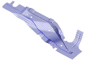 |
| Figure 1: Making multiple section cuts along an axis and then calculating the length of each cut allows a designer to estimate a part's width at any point for the flat blank. |
Once a strip layout has been designed, the die design can be built around that strip concept, but enough room must be left so that the overall design can accommodate substantial changes if the calculated flat blank must be altered.
Once the die forming stations are built so that they can be used for development of the final blank, the die can be assembled to that point. Then, a strip of material must be created to run through the form stations in the die to test how the forms produce.
One of the most useful tools that the author has found for this task is a laser burner. A laser burner is similar to wire electrical discharge machining (EDM) equipment in its function but does not use a wire. Many service companies offer laser burning for occasional users, or a company that does a great deal of this type of work might investigate whether purchasing a machine is justified.
A strip layout can be built by arranging four or five copies of the flat blank on a strip and then sending the geometry to a service company or in-house department to burn the strip directly from that setup. The strip should include the pilot holes that will be in the die or some other method to register each progression when hitting the strip for development purposes.
From the strip layout geometry, a designer should choose a central reference point on the computer. Then, the designer should create a grid of lines at 0.100-inch increments along the axis of the width of the strip. This should be plotted at a scale of 1 to 1.
When the strip is returned by the service company or in-house department, a designer should take the time to ink up each progression with die makers' ink blue. Then, the plot should be overlain onto the outer surface of the strip. A small center punch mark should be placed through the plot and onto the strip for reference. This ties the strip layout to the strip in terms of geometry.
Next, the designer should use a height gauge to scribe the same lines on 0.100-inch increments from the strip layout onto the strip itself. At this point, the strip should be hit in the die form stations. The designer should hit two or three of the progressions so that the final form hits as it will in the completed die. This ensures an accurate form.
After all this has been done, the final formed part can be cut from the strip, and the trim line can be analyzed using a check fixture, coordinate measuring machine (CMM), or similar device. By counting from the central reference point to the scribed line on the part, the designer can determine the exact point in the flat blank where the trim line needs to be adjusted. A scale can be used to measure the trim line at that point to determine how much adjustment is needed.
After repeating this process around the part geometry and adjusting the flat blank layout, a newly developed flat blank layout will emerge. This new layout, in turn, should be used to generate a new strip that should be sent to the service company or in-house department. Repeating this process until a tolerable part trim line is achieved usually yields a good-part flat blank layout in from three to five attempts.
Now, the die blanking steel can be completed to finish the die building process. Once an acceptable part layout has been achieved, a designer should burn and hit one more strip—just to be safe—to prove consistency before wire burning the blanking die steel.
Once the die is completed, the original design should be updated to reflect any development changes. That way, if any die blocks need to be replaced in the future, a designer can simply pull up the design on a workstation and search out the detail to be remade.
This leads to another aspect of modern die design. Most customers now want 100 percent detailed designs so that after future maintenance or engineering changes, die blocks can be replaced simply by regenerating the blueprint for that particular detail and remanufacturing it. Because of the expense involved in tooling up a part for manufacture and the longevity of dies in the production place, having well-documented designs that include engineering changes and developments is critical.
In recent years, most computer-generated designs have been archived onto magnetic media of some type, including floppy disk, hard disk, or tape backup. This is a good idea, but magnetic media of any type have an expected shelf life of from two to five years, in most instances. After that, the magnetic electrons on the media simply begin to dissipate. That can create a problem if seven years later, a customer wants a new die built with only slight part modifications.
One option to consider is a CD-ROM burner or writer, as some refer to it. A CD-ROM disk has a shiny surface that is burned with a laser to etch binary marks onto it to record data. These disks have much longer shelf lives—estimates range from 10 to 50 years. In addition, they can store 650 megabytes per disk. Designs are getting larger and larger to account for 100 percent detailing, 3-D requirements, etc., but each compact disk can store several large designs for a customer at minimal expense.
The ideas presented in this article are suggestions based on how the author has handled some problems he has encountered, although other, possibly better, methods may be available. Stamping professionals should be creative when presented with a task and should deduce what would be the best method of attack in each situation. No two problems are exactly the same, so they cannot always be solved in exactly the same manner.
Software packages are available for calculating flat blanks for such 3-D problems. Although the author has not evaluated them, the packages may aid in die design.


The Fabricator is North America's leading magazine for the metal forming and fabricating industry. The magazine delivers the news, technical articles, and case histories that enable fabricators to do their jobs more efficiently. The Fabricator has served the industry since 1970.
start your free subscription
Easily access valuable industry resources now with full access to the digital edition of The Fabricator.

Easily access valuable industry resources now with full access to the digital edition of The Welder.

Easily access valuable industry resources now with full access to the digital edition of The Tube and Pipe Journal.

Easily access valuable industry resources now with full access to the digital edition of The Fabricator en Español.
In this episode of The Fabricator Podcast, Caleb Chamberlain, co-founder and CEO of OSH Cut, discusses his company’s...


