


Contributing Writer
 |
One of the best ways for stampers to compete in this market is by maintaining the highest quality standards and using technology to combine operations wherever possible.
Performing stamping and tapping in a single operation, for instance, helps reduce labor costs and increase quality while finishing parts at a fast rate. In the past many metal stampers often shied away from quoting jobs for stamped parts with tapped holes because of the cost of performing secondary tapping operations, a lack of understanding of in-die tapping, or a bad experience with in-die tapping.
With modern tapping heads, speeds have been increased, maintenance has been reduced, and design methods have changed. Tapping-head engineers can provide customers with the necessary information and support to quote an in-die tapping job knowledgeably, and they can work closely with tool and die designers throughout the design process. This cooperation between tapping-head engineers and prospective customers benefits everyone by limiting potential problems before they exist.
Initial Investment. The cost of building a tapping die, including the tapping unit, is generally less than that of building a secondary high-speed tapping machine. Secondary tapping machines usually are dedicated to a single part, but a tapping unit can be changed from die to die, reducing the initial cost of subsequent tapping dies and making lower-volume tapped stamped parts feasible for in-die tapping.
The cost of stamping parts with multiple tapped holes can be further reduced using a multispindle tapping unit. The initial cost of multispindle tapping units per hole tapped typically is about 30 to 40 percent less than that of an individual tapping unit.
Multispindle tapping units usually are dedicated to a single die, so they cannot be interchanged. However, the tapping heads are compact, and the decreased die space required to accommodate the tapping die helps reduce initial tooling costs.
Labor Requirements. Eliminating a secondary tapping operation also eliminates related handling and feeding costs. In-die tapping enables the press operator to produce completed tapped parts in one operation. Of course, inspection and tap changes still are required. New sensor technology can help reduce inspection costs, and a twist-lock lead screw assembly can help speed tap changes.
Production Rates. New high-speed tapping units are no longer the limiting factor in how fast a tapped part can be produced. Instead, the size of the tap and the material being tapped determine the ultimate production rate of a tapped stamped part.
Some stampers are running modern tapping units close to 200 strokes per minute (SPM), producing millions of tapped stamped parts monthly. These high production rates usually are limited to nonferrous metal parts and those with small-diameter tapped holes. As the diameter of the tap increases, production rate decreases. Other factors affecting SPM are the type of material being tapped and its hardness.
It can be difficult to convince a metal stamper to slow down the press to perform the tapping operation. Even with today's modern tapping units, some compromise in press speed may be necessary. When these compromised press speeds are not acceptable, metal stampers often build two-, three-, or four-up dies to minimize press time.
Even so, it is important to remember that with in-die tapping, the part is finished in one operation with one operator. Consider that an automotive part with a 5/16-18 tapped hole may run at 90 SPM without tapping and then be transferred to the tapping operation, which may run at 30 to 40 SPM. The same part using in-die tapping will run at a rate of 60 SPM to produce a completed part.
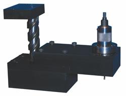 |
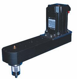
| Figure 1 Top-down tapping units can run at high speeds and are suited for high-volume jobs while requiring minimal maintenance. A twist-lock lead screw assembly allows fast tap changes. |
Another issue often overlooked is thread quality. When parts are tapped in the die, because of the nature of a progressive die, the location of the hole being tapped should always be within 0.001 or 0.002 inch of the center. This location helps increase tool life and thread hole accuracy.
Almost all metal stamped parts with threaded holes can be tapped in-die. When the hole location or part configuration does not make it practical to tap in the die with standard off-the-shelf tapping units, custom-designed units with single- or multihole capabilities are available to tap in any direction.
Several types of tapping heads are available for different applications.
 |
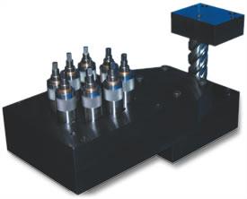
| Figure 2 When strip lifts increase beyond the capacity of a standard top-down unit, tapping from the bottom up is an option. Bottom-up tapping units can run at similar speeds as top-down tapping units for millions of nearly maintenance-free strokes. |
Top-down Tapping. Top-down tapping units—single or multispindle—are suitable for flat running parts with minimal strip travel (see Figure 1). With a twist-lock lead screw assembly on top-down units, tap changes can be made in seconds rather than minutes, reducing downtime. These units typically can be used in high-volume, high-speed applications and are capable of running at more than 200 SPM.
Bottom-up Tapping. As strip lift, which is the distance the material has to lift above the lower die to clear for extrusions or forms to progress to the next station, begins to increase, tapping from the bottom up is one way to compensate for the increase in material movement (see Figure 2). With bottom-up tapping, the material is pushed down onto the tapping head, allowing the tapper to thread the part much in the same way as if the part ran flat. Rather than using the revolutions required by top-down tapping to compensate for material lift, the bottom-up tapper uses only the press strokes needed to push the part down onto the tapper.
Bottom-up tappers are available in single- and multispindle configurations and can run at similar SPM as top-down tapping units while maintaining the same serviceability.
In some cases, bottom-up tapping requires the strip to be removed from the die to perform tap changes. If there is adequate room underneath the die, a twist-lock lead screw assembly can eliminate the need to remove the strip. Also, long stripper travels may be required to hold the material the length of time necessary to tap the part.
 |
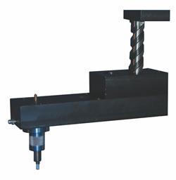
| Figure 3 Self-contained strip-following tapping units can increase tapping production rates while maintaining standard stripper travels. |
Strip-following Tapping. Self-contained strip-following tapping units are available in single- and multihole configurations (see Figure 3). They can be used with low to moderately high strip lift, but usually not exceeding 2 1/2 in. of lift.
A strip-following tapping unit begins to thread the part as soon as the material is fed into position. This allows a large tapping window during the press cycle, translating into low gear ratios. Low gear ratios mean the press can run fast and still maintain the proper revolutions per minute (RPM) on the tap.
In lower-stroke presses with moderate material lift, enough press stroke may not be available to perform the tapping operation and compensate for material lift, in which case a strip-following tapping unit may be the only alternative. In higher-stroke presses running large-diameter tapped holes, production rates sometimes can be doubled using all available press stroke for the tapping operation.
 |
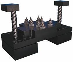
| Figure 4 The threading operation in a servo-driven tapping unit functions independently of the press stroke, which can be useful with large-diameter taps. |
Consider a 1/4-in.-thick part with a 5/16-18 hole and 1-in. strip lift that needs approximately 9 1/2 revolutions to complete the tapping operation in a 12-in.-stroke press. A conventional tapping unit working from the bottom up with a 2-to-1 gear ratio (two revolutions per 1 in. of stroke) requires a stripper to hold the material for about 4.75 in. This 4.75-in. window allows the press to run 30 to 35 SPM and still maintain the proper RPM on the tap.
The same part with a strip-following tapping unit with a 1-to-1 gear ratio can run at 60 to 65 SPM while maintaining the standard 3/4-in. stripper travel. The strip-following tapping unit allows a tapping window of 9.50 in., which reduces the RPM of the tap by half, doubling the production rate.
Servo-driven Tapping. In a servo-driven tapping unit, the threading operation functions independently of the press stroke, which can be beneficial when running large-diameter taps (see Figure 4). Servo-driven units can tap for more than 180 degrees of the press cycle at specified RPMs and rapid-reverse in a shorter cycle time than can a conventional mechanically driven unit.
Servo-driven units can be used in transfer presses, multislides, and high- and low-stroke applications. They can tap from the top down or bottom up and work in multitap applications. Stripper travels generally are similar to or greater than those of conventional tapping units.
The cost of a servo-driven unit usually is two to four times that of its mechanical counterpart. Also, because of the speed and torque limitations of servo units, mechanical units often perform equally well, especially when using strip-following technology.
The following guidelines may be helpful in making an in-die tapping operation successful.
Determine the best method of in-die tapping for the application. Parts can be tapped in a variety of ways. An experienced tapping-head engineer should be able to determine the best solution for the application.
The tapping-head engineer should be willing to work closely with the tool designer to eliminate potential problems. This is particularly important for tool designers unfamiliar with in-die tapping. Equally important, the tapping-head engineer should be able to estimate SPM by calculating the surface feed per minute of a particular tap on a particular material. These calculations usually are on the conservative side, but will provide a knowledgeable base on which to quote.
Determine which tapping head design is simplest for both the designer and engineers to work with. Some tapping units may require a shimming process to adjust the height of the tap within the die, while others use a twist-lock lead screw assembly.
Determine which design is not only the most cost-effective initially, but cost-effective while in production. The base price of some units may not include all the necessary hardware and may require additional installation work by the tool shop. Some tapping units may require a rigid maintenance program, increasing downtime and shop time, while other tapping units may run for tens of millions of parts nearly maintenance-free.
William Pfister is president of Automated Tapping Systems, 22 Davos Road, P.O. Box 1033, Brick, NJ 08723, 732-899-2282, fax 732-899-0277, tapping30@aol.com.


The Fabricator is North America's leading magazine for the metal forming and fabricating industry. The magazine delivers the news, technical articles, and case histories that enable fabricators to do their jobs more efficiently. The Fabricator has served the industry since 1970.
start your free subscription
Easily access valuable industry resources now with full access to the digital edition of The Fabricator.

Easily access valuable industry resources now with full access to the digital edition of The Welder.

Easily access valuable industry resources now with full access to the digital edition of The Tube and Pipe Journal.

Easily access valuable industry resources now with full access to the digital edition of The Fabricator en Español.
In this episode of The Fabricator Podcast, Caleb Chamberlain, co-founder and CEO of OSH Cut, discusses his company’s...


