


Next-generation large-tonnage presses rely on new software for virtual integration
How system design can make flexible systems easier to manage
Instead of separate simulation software for press design, transfer design/programming, and die design, a new virtual engineering approach integrates all areas of system development before the press system is even built. Here, simulation shows part deflection.
Henry Ford's mass production philosophy "… any color that he wants so long as it is black" is a distant memory for stampers in automotive vehicle production. It is also an obsolete approach to parts production because stampers have to produce an increasing variety of components on large stamping presses.
In large-part production, forming a roof or outer door panel is quite different from forming a fender or body side. This is why system flexibility is needed for the automotive OEM or tier stamper. Flexibility is no longer an option; it is a requirement.
While press systems have been designed with similar subsystems and components to simplify maintenance, a hurdle still remains for them to integrate the operating functions for varied production.
Integrating Operating Functions
In the past press system specialists designed the specific forming and process requirements into the press system with limited production information available to them. Today these requirements and process adjustments change with changing production and need to be optimized on-site as quickly as possible.
Typically, flexible press systems that can produce a variety of parts are challenging to deal with in an existing production environment. For those considering whether to invest in a new press system or to keep an old system in service, investment costs and the increased complexity of flexible systems are concerns.
In some cases, large, traditional mechanical-drive systems that are custom-designed for specific applications can be more costly than flexible, servo-controlled, programmable-drive systems.
As technology for large press systems evolves, new, large-scale, servo-driven presses with servo-driven transfers (and even servo-controlled robot centering stations and servo-adjustable end-of-line systems) are taking the needs of operations to an entirely new level of flexibility.
Now standard flexible systems have a wide range of adjustments so operators can set the system to the specific, optimal settings for each part.
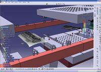
To simplify the process, new software is available (see Figure 1) that provides virtual integration of the slide motion and the transfer movement in a way that (1) allows the press to be built, (2) the transfer to be integrated, and (3) the die to be built in the most efficient way for the overall system. In lieu of separate pillars of development—press design, transfer design/programming, and die design—this virtual engineering approach integrates all areas of system development—before the press system is even built—which can help stampers to procure and implement a much more efficient and productive flexible press system (see lead image).
Overview of System Flexibility
A few of the functions that can make flexible systems easier to operate are:
A servo-driven press's production can be simulated showing virtual integration of the slide motion and the transfer movement in a way that allows the press to be built, the transfer to be integrated, and the die to be built.
- Destacker
- Magnet adjustments (amount, angle position, distance)
- Stack positioning (height, location accuracy)
- Destacking (movements, cup positions)
- Double-blank detection (position, distance)
- Washing (type of fluid, amount, pressure)
- Reoiling (amount)
- Part positioning in centering station (robots, position, movements)
- Transfer
- Transport (tooling position, lift movements, overlap with feed motion, area of part detection, acceleration, speed)
- Positioning (vacuum control, position, drop of height)
- Tilting (part orientation, reducing lift stroke)
- Spreading (part orientation, clearing die components, range of movement)
- Cushion
- Preacceleration (position, speed)
- Binder control (equalizer plates, draw beads, size)
- Tonnage settings (left-right, front-back verification; changing through the draw)
- Press
- Adjustable press characteristics (draw velocity, stop at bottom dead center, speed limitations for die components)
- Transfer timing (opened position for defining clearance to transfer)
- Die functions
- Cam control (relative to transfer)
- Part sensing (position, timing)
Production changes on traditional press equipment can be difficult because efforts to produce a quality part out of the line can slow throughput rates. It has been the challenge of many to try to meet the output rates that the original investment calculations were based on. A system that is forced to operate faster without equipment upgrades can be expected to break down.
Optimizing a press system to run efficiently and flexibly requires looking beyond output rates to quality and system availability in terms of fast changeovers and short tryout and start-up times to provide additional production time to run other jobs. This means optimizing the overall equipment effectiveness.
It would be difficult to find any one person capable of defining the ideal settings for all of these system parameters while operating a press system with 10 new die sets a year. This requires specialists, integrating many people on-site to tap into their experience and expertise. However, bringing these specialists together could be expensive.
Today, specialists have integrated their expertise to develop system tools in a digital press shop using virtual simulation of the entire press system. The destacker, transfer, cushion, press, and die functions can be optimized and integrated even before the press system is built. This improves the flexibility and ease of use of a new system when it is delivered to a press shop.
| Process Steps and Support Required for a Digital Press Shop Environment | |
|---|---|
| Step | Digital Press Shop Information |
| Draw Simulation | Formability |
| Process Flow Chart | System dimensions, number of stations, tonnages, transfer capabilities |
| Transfer Flow Chart | Definition of suction cup location and transfer movements Definition of space volume available for die structure; definition of system loads and related output rates. |
| Die Design | Library of die elements, available sizes (based on press system and transfer movement) |
| Optimized Settings | Further overall equipment effectiveness improvements |
| System Setup | Basic die recipe data for all parameters |
System Planning, Simulation
Production should start immediately after a new press line is installed. Therefore, during the construction phase of a new press line, projects must be planned before system tryout capabilities are available.
A digital press shop provides a range of planning and simulation capabilities to verify the results of planned production without having a physical model. Its offline programming tools will also help to increase the availability of press lines during production, speeding changeovers and improving initial quality.
For example, 2-D curves have been sufficient for planning production on conventional crossbar press lines. Now, with simulation, it is possible to provide all of the requirements and orientation capabilities of the new crossbar feeder into the planning process. To predict and optimize the stroke rate, it is necessary to consider the actual behavior of the control system.
Virtual Process and Transfer Planning for Press Design
Usually the system process is based on the results of feasibility studies that provide predicted in-process-parts, working directions and effective geometry.
Based on these results, the process flow chart redefines all sheet metal faces and geometry for NC-path planning. During this planning step, the process planner can use the virtual model of the press line to adjust and align the part symmetrically with the cushion pins; define the minimum height to ensure enough space for deep drawing; or set a sufficient incline for the scrap slides.
The correct rotation of the part will ease the drawing process and can minimize the number of cam units. The main questions to answer are: Is part transfer possible? Are the stroke rate and clearance sufficient? For this purpose, the transfer planner selects a suitable curve, primarily by considering the necessary lift height of the part. The part positions may influence a change of the basic curve.
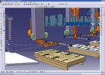
Part production volume is defined by press and transfer movement and available die area.
One important step for adopting the curves is to collect the part positions and the corresponding crossbar positions. Considering the relative position between the part and crossbar fixes the target position of the crossbar at the associated station. The inverse kinematics calculation delivers the axis parameter for this position. The virtual system displays pick-and-place position and other transfer defining parameters, and the planner can adjust these parameters within given limits.
Simulation results are only as good as the simulation model they are based on. This is especially the case for the synchronization of the transfer and slide motion given by the control unit. So, the real control behavior has to be considered.
After the planner has confirmed the path parameters, the press control calculates the synchronized motion curves for transfer axes and slides. These curves are sent back to the digital press shop. Then, the motion of all components can be checked for collision, and tracking curves can be generated to judge the clearance. In addition, the press control provides the stroke rate for the calculated curve.
When the stroke rate and clearance simulations are complete, the next step is the tooling design. Starting with suction cup positions, it is possible to predict the space available to install the tooling between the suction cup and the adapter of the crossbar. The digital press shop environment even supports the tooling definition by building a customized parametric tooling library and builds the resulting bill of material based on the tooling setup.
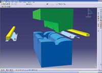
In the virtual system, the motion of transfer components, sheet metal parts, and tooling assemblies provides the basis to calculate the remaining space or volume available for the die design.
After die design is complete, collision detection between all moving components in the press line, transfer dies, and tooling can be performed. In addition to the view of production, the setup process also has to be checked, when dies and tooling are exchanged by moving the bolsters in and out of the press line.
Outlook
While the concept of the fully integrated software and hardware for large-press design is relatively new, advances that are useful to stampers and die designers are already on the horizon. It is expected that there will soon be the capability to go beyond the definition of the volume of space used by picking and placing, and also to define the die envelope for die design—considering all cam units and other moving parts.
Then the die designer will have a specifically defined volume in which to work. This will improve the integration of the die into the press system before the die or press is actually constructed, in most cases.
A virtual die tryout tool, currently under development, calculates with a given slide motion curve the displacement of all cam units with consideration of their geometry. The kinematics can be defined with a dedicated user interface. Unexpected and undesired collisions are recorded and displayed in a convenient manner for the die designer, so that the die functionality can be checked in a short amount of time.
One additional step to a more realistic simulation will be integration of finite element method tools into motion planning. The calculation of vibration of sheet metal parts and forces upon suction cups is generally possible with integrated FEM tools, but integrated visualization of vibrating components in a moving press line has yet to be supplemented.
Dietmar Schoellhammer, Schuler Presses (Schuler Inc. affiliate), 7145 Commerce Blvd., Canton, MI 48070, 734-207-7200,info@schulerinc.com, www.schulerinc.com. Bernhard Loske is senior consultant, Dassault Systèmes of America Corp., 6320 Canoga Ave., Trillium East Tower, Woodlands Hills, CA 91367, 818-673-2243, www.3ds.com.
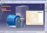
Cam movement simulation is based on contact, considering spring load.
About the Authors
About the Publication

subscribe now

The Fabricator is North America's leading magazine for the metal forming and fabricating industry. The magazine delivers the news, technical articles, and case histories that enable fabricators to do their jobs more efficiently. The Fabricator has served the industry since 1970.
start your free subscription- Stay connected from anywhere

Easily access valuable industry resources now with full access to the digital edition of The Fabricator.

Easily access valuable industry resources now with full access to the digital edition of The Welder.

Easily access valuable industry resources now with full access to the digital edition of The Tube and Pipe Journal.

Easily access valuable industry resources now with full access to the digital edition of The Fabricator en Español.
- Podcasting

In this episode of The Fabricator Podcast, Caleb Chamberlain, co-founder and CEO of OSH Cut, discusses his company’s...


