


Regional Sales Manager

As steels have improved and become stronger, the methods needed to achieve optimal results to perforate that steel have had to improve as well. The tried-and-true approaches that worked well to stamp first-generation steels are not as effective to stamp the new advanced high-strength steels (AHSS).
Tests were conducted on AHSS to determine optimal punch-to-die clearances, shear angles, and punch angles. Test results indicated that 12 to 15 percent punch-to-die clearances and -15- to +15-degree shear angles provided the longest punch and die life, and a 7-degree conical shear angle created the smallest burr growth.
A collaboration of the Auto-Steel Partnership, its automotive OEM, steel committee partners, and advisory members and Dayton Progress constructed a 13-station progressive-die set to use as a test part to gather data for evaluation (see Figure 1).
Tests were conducted on a nonfunctional part strip to examine several tooling applications, including bending, forming, trimming, applying draw beads, punching slots, and perforating slots. AHSS tool steels dual-phase 780 (DP780) and dual-phase 980 (DP980) ran over 300,000 cycles, and the part from every thousandth hit was saved for analysis. After every 5,000 cycles, researchers stopped the press to inspect the various die details for indications of tool wear or damage.
Researchers inspected the heavy-duty ball lock punches and press fit buttons for potential edge chipping or galling. They also saved the parts to evaluate hole quality and sectioned the parts to examine the hole shear and measure part burr height.
Figure 2 shows the six-stage progression of perforating a hole. Note the shock the material encountered at punch impact. This shock is even more pronounced when piercing high-strength materials. The shock wave is very high at impact, and then it begins to flatten out and become more controllable at penetration. The impact load is reduced when the punch breaks through the material.
At snap-through, however, the tooling and press undergo another shock. Typically this is the point at which a punch head pulls off or punch tips chip or break. Then the punch bottoms out before withdrawal from the material.
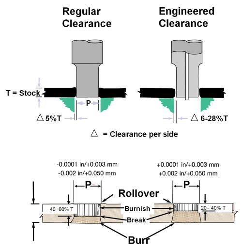
Clearance is the distance between the punch and the die button. This is depicted graphically as delta (∆). Experience with mild steels indicates a recommended clearance of 10 percent total, or 5 percent per side.
Regardless of the material being stamped, its thickness, or press speeds, a 5 percent clearance is adequate for many applications. However, as steel chemistries have changed to strengthen the materials, the required optimal clearances also need to change. The clearance for AHSS should expand 6 to 28 percent, depending on the steel type and its thickness.
Figure 3 shows that the regular hole has more shear or burnish; this typically is in the 40 to 60 percent range. Once the material hits its tensile limit, the material breaks and the slug snaps out, creating a burr on the surface. Less shear or burnish occurs with the engineered clearance—just 20 to 40 percent. This creates a larger break but a smaller burr.
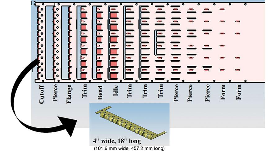
Figure 1
A 13-station progressive-die set was used as a test part to gather data for evaluationof optimal die clearances, pierce angles, and shear angles to punch advanced highstrength
steels.
The trial was undertaken to determine a range of optimal clearances for AHSS, beginning with a range of 5 to 30 percent. Burr height was measured in inches along with other metrics over the number of hits. After more than 30,000 hits, the 10 to 15 percent clearance range appeared to provide rather consistent burr height results.
Testing resumed on the DP980 material with a narrowed clearance range of 8, 10, 12, and 15 percent to verify the earlier findings. The 15 percent clearance produced the best hole quality and smallest burr.
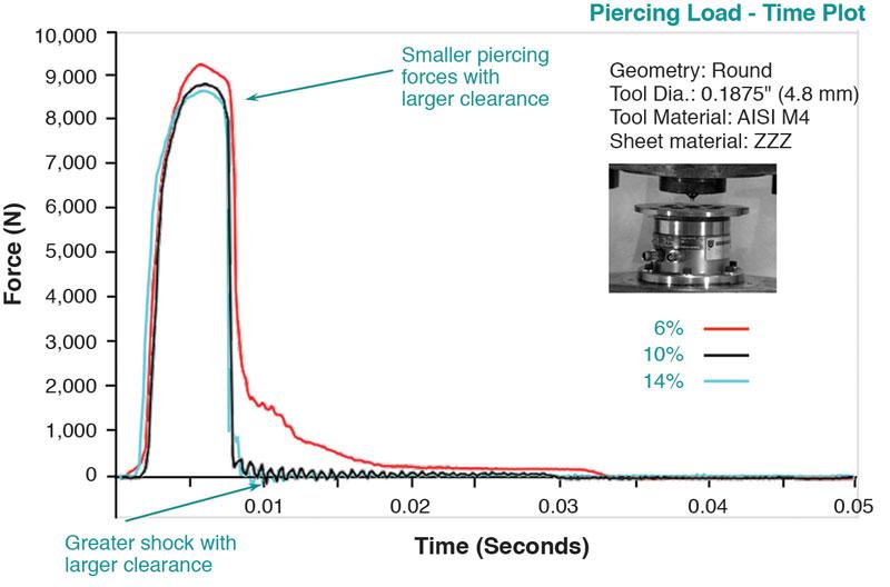
Figure 4 depicts the perforation load on the punch tip for DP780 AHSS at varying die clearances.
Clearances tested were 6, 10, and 14 percent. The 6 percent clearance generated a little over 9,000 newtons of force. As the clearance was increased to 10 percent, the load force decreased to 8,800 N. At 14 percent clearance, the force dropped to 8,300 N. In general, as clearances increased, the piercing load decreased on the punch tip, which extended tool life.
Creating a larger hole also extended tool life; however, the impact or shock as the punch initially struck the material was greater.
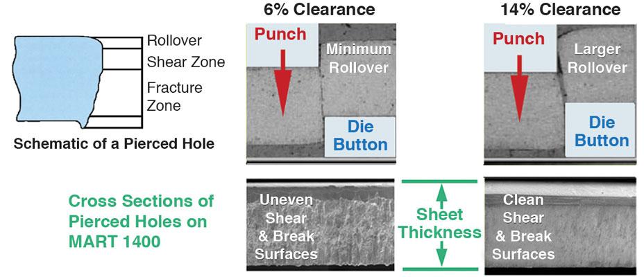
Figure 5 illustrates how different die clearances affect hole quality characteristics.
When the side view illustrations of the 6 and 14 percent clearance holes are compared, it is apparent that the 6 percent has minimal rollover and rather severe, uneven shear and break surfaces. The burr edge is very jagged and large.
The 14 percent clearance has clean, even shear and break surfaces with slightly larger rollover. The burr surface is even and minimal.
Generally, for a given hole size, as material clearance increases, the hole quality improves, and smaller burrs are produced. There is a tradeoff, however. There is a tendency for rollover to increase as well, which may affect how the hole can be used. If the hole is intended for a noncritical application, such as a hole for a bolt, it may not matter. But if the hole is needed for a more precise application, such as for in-die tapping, the amount of rollover is critical.
Normally, the ideal perforating situation is at a 90-degree angle where the punch descends vertically into the material. To measure the effect of different pierce angles, researchers tested pierce angles from -30 degrees to +30 degrees, in 5-degree increments.
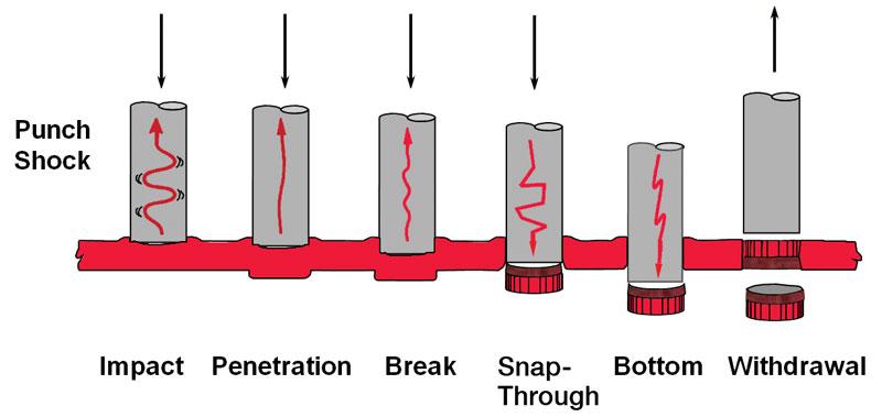
Figure 2
During the six-stage progression of hole punching, impact is highest at snap through. Impact is even higher when penetrating AHSS.
At extremes of -30 degrees and +30 degrees, punch and button life were adversely affected. What is an optimal range for angle perforating? Testing after 100,000 cycles indicated that the optimal range to extend punch life is ±15 degrees—either way. Within this range, the punches showed minimal abrasive wear and no point chipping. Outside of this 15-degree range, the punches experienced more severe wear, and die buttons showed signs of chipping and slight elongation.
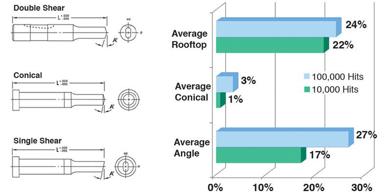
In addition to clearances and pierce angles, researchers also investigated the effect of shear angles on hole quality in AHSS. Three standard types of pierce shear angles—single shear, conical, and double shear (or rooftop)—were tested at a 7-degree angle using standard, commercially available punch tool steels.
Figure 6 illustrates the burr height growth from 10,000 to 100,000 cycles.
The test results showed the conical shear ranking as the best, with burr growth of only 1 to 3 percent. The rooftop (double) shear was second best with burr growth of 22 to 24 percent. The double shear is most effective on shaped point punches, while the conical shear is best on round punch points.
So once a hole is punched, what does the ensuing hole really look like? What is going on inside the hole?
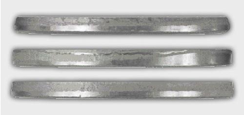
Examining the slugs generated by the perforating operation is a reliable way to inspect hole quality. Slug analysis is a great starting point for investigating problem areas.
Analyzing the slugs is a way to see how much punch force is dispersed on the material, and how much shear and break occur within the hole and burr generation. You can feel and see the part burr, but you cannot see inside the hole to see the shear and burnish and break. Slugs provide this information.
Figure 7 shows a trio of slugs.
Slug control is a real opportunity to improve and increase punch and die button life and increase part productivity. Slug pulling can ruin the punch and die detail. In general, a taper relief die button adequately controls the slug. Taper relief die buttons offer a longer service life because they can be sharpened more frequently. They also allow the slugs to clear properly without stacking up in the die button relief. A combination of a tapered relief die button with shear angles on a punch or with an ejector pin greatly reduces the probability of the slug sticking to the punch tip.
For problematic slug pulling situations, engineered slug control works very well: Rifled grooves hold the slug in the landing of the first hit. Subsequent press strokes release the first slug into the taper relief and trap the next slug in the button’s landing.
A note of caution: Avoid over- entry or pushing the punch tip past the die button land.
This interferes with the slug getting locked in the slug control grooves.


The Fabricator is North America's leading magazine for the metal forming and fabricating industry. The magazine delivers the news, technical articles, and case histories that enable fabricators to do their jobs more efficiently. The Fabricator has served the industry since 1970.
start your free subscription
Easily access valuable industry resources now with full access to the digital edition of The Fabricator.

Easily access valuable industry resources now with full access to the digital edition of The Welder.

Easily access valuable industry resources now with full access to the digital edition of The Tube and Pipe Journal.

Easily access valuable industry resources now with full access to the digital edition of The Fabricator en Español.
In this episode of The Fabricator Podcast, Caleb Chamberlain, co-founder and CEO of OSH Cut, discusses his company’s...


