Professor Emeritus and Director - Center for Precision Forming
- FMA
- The Fabricator
- FABTECH
- Canadian Metalworking
Categories
- Additive Manufacturing
- Aluminum Welding
- Arc Welding
- Assembly and Joining
- Automation and Robotics
- Bending and Forming
- Consumables
- Cutting and Weld Prep
- Electric Vehicles
- En Español
- Finishing
- Hydroforming
- Laser Cutting
- Laser Welding
- Machining
- Manufacturing Software
- Materials Handling
- Metals/Materials
- Oxyfuel Cutting
- Plasma Cutting
- Power Tools
- Punching and Other Holemaking
- Roll Forming
- Safety
- Sawing
- Shearing
- Shop Management
- Testing and Measuring
- Tube and Pipe Fabrication
- Tube and Pipe Production
- Waterjet Cutting
Industry Directory
Webcasts
Podcasts
FAB 40
Advertise
Subscribe
Account Login
Search
R&D Update: Predicting springback in air bending, straight flanging
- By Taylan Altan, Ph.D.
- October 9, 2003
- Article
- Bending and Forming
Editor's Note: This column was prepared by the staff of the Engineering Research Center for Net Shape Manufacturing (ERC/ NSM), The Ohio State University, Professor Taylan Altan, director.
Air bending and straight flanging are the most prevalent types of bending in sheet metal forming. Predicting springback precisely during die design is key to obtaining tight part tolerances and controlling the process.
Bending Operations
In air bending, or free bending, a sheet is supported by two shoulders of a stationary die (see Figure 1a). The die is designed to be deep enough to prevent the punch and the workpiece from bottoming out. The required bending angle is determined by the die opening and punch displacement.
Straight flanging is a forming operation in which one end of the sheet is bent down along a straight line (see Figure 1b). The other end of the sheet is restrained by a pad and blank holder force. Flange length can be changed easily, and the bending angle can be controlled by the punch stroke.
In bending operations, common methods used to reduce springback or control the bending angle after unloading are double-die bending, coining, and rotary bending. Double-die bending is two straight flanging operations acting on the workpiece one after another (see Figure 1c). It can be used to iron and coin a part's radius to reduce springback.
In coining operations, compressive stress is applied between the tip of the punch and the die surface (see Figure 1d). This can reduce springback but results in increased punch force.
Rotary bending uses a rocker that simultaneously holds and bends the material (see Figure 1e). The rocker acts like a pad, clamping the workpiece in position and overbending it to compensate for springback. This operation can achieve more than 90 degrees of bending angle and can significantly reduce punch force.1
 |
Controlling Springback
Springback must be predicted in bending operations and then the punch position adjusted accordingly. Springback is an elastic recovery of a material after unloading. In Figure 2,2the final bend angle after springback (af) is smaller than the bend angle before springback (ai), and the final bend radius after springback (Rf) is larger than the bend radius before springback (Ri).
It is difficult for design engineers to predict springback because many variables affect it, such as material properties, tool geometry, sheet thickness, and punch stroke. As a rule, however, the smaller the punch radius, the smaller the springback, and the greater the bending angle, the greater the springback.3
 |
| Figure 2 The final bend angle after springback (af) is smaller than the bend angle before springback (ai), and the final bend radius after springback (Rf) is larger than the bend radius before springback (Ri). |
To enhance machine productivity and control springback, press brake manufacturers such as Amada, LVD, and TRUMPF developed control systems to control the punch stroke. These control systems import workpiece drawings from CAD and automatically generate a handling program and synchronize it with the press brake's computer-controlled movements.
COPRA® LaserCheck, developed by data M Engineering, measures bending angles in press brakes for different material types and thicknesses. It enables an operator to determine the exact bending angle during production with a built-in semiconductor laser with line optics and a camera with strain gauges. The control unit automatically corrects the punch stroke during the bending process. Similar precise measuring systems are used in TRUMPF and LVD press brakes.
For practical purposes, a mathematical model was created. The model makes it possible to control springback as a function of punch displacement in the air bending process.4Such a mathematical model to predict springback during air bending and straight flanging was developed at ERC/NSM5,6and has been implemented into a computer program called BEND.
 |
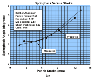
| Figure 3a Predicted springback angle and punch stroke show good agreement with the experiment. |
BEND Program
The BEND program uses a Windows® platform to compute springback in air bending as well as straight flanging. The required input data are the material properties (flow stress, Young's modulus, Poisson's ratio, sheet thickness, and width), tool dimensions (punch radius, die radius, and die opening), and process parameters (desired bending angle and friction coefficient).
This program provides three kinds of outputs:
- Process information (springback angle and bending angle)
- Press control information (punch force versus punch stroke)
- Geometry information (maximum strain and deformed profile)
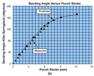
Springback values, determined in air bending tests reported by Raghupathi,7 were predicted by the BEND program. Aluminum alloy 2024-O was used in these tests. The predicted curves of a springback angle versus punch stroke and desired bending angle versus punch stroke were compared with the experimental data (see Figure 3). The results showed good agreement with the experiment and indicated the software's reliability.
 |
| Figure 3b |
It takes less than one minute to run the BEND program. The effects of process parameters and material properties on springback can be estimated using the program, which may reduce the time needed to adjust the press stroke and to conduct production tryouts.
Taylan Altan is a professor and director of the Engineering Research Center for Net Shape Manufacturing, 339 Baker Systems, 1971 Neil Ave., Columbus, OH 43210-1271, 614-292-9267, fax 614-292-7219, www.ercnsm.org. The ERC/NSM conducts research and development; educates students; and organizes workshops, tutorials, and conferences for the industry in stamping, tube hydroforming, forging, and machining.
Notes
1. W.H. Cubberly and R. Bakerjian, Tool and Manufacturing Engineers Handbook, 4th ed. (Dearborn, Mich : Society of Manufacturing Engineers, 1989), II, Chapter 10, p. 16-17.
2. S. Kalpakjian, Manufacturing Processes for Engineering Material (Meno Park, Calif. Addison-Wesley Professional, 1997).
3. S.D. Benson, Press Brake Technology— A Guide To Precision Sheet Metal Bending, Dearborn, Mich: Society of Manufacturing Engineers, 1997).
4. P.S. Raghupathi, M. Karima, and T. Altan, "A Simplified Approach to Calculate Springback in Brake Bending," in proceedings from NAMRC XI, May 1983, pp. 165-171.
5. C.T. Wang, G.L. Kinzel, and T. Altan, "Process Simulation and Springback Control in Plane Strain Sheet Bending," SAE paper No. 930280, 1993.
6. C.T. Wang, G.L Kinzel, and T. Altan, "Mechanics of Bending and Flanging and User's Manual for Computer Programs BEND and FLANGE," ERC/NSM Report No. ERC/NSM-93-29-S, The Ohio State University, 1993.
7. Raghupathi et al.
About the Author

Taylan Altan, Ph.D.
Related Companies
subscribe now

The Fabricator is North America's leading magazine for the metal forming and fabricating industry. The magazine delivers the news, technical articles, and case histories that enable fabricators to do their jobs more efficiently. The Fabricator has served the industry since 1970.
start your free subscription- Stay connected from anywhere

Easily access valuable industry resources now with full access to the digital edition of The Fabricator.

Easily access valuable industry resources now with full access to the digital edition of The Welder.

Easily access valuable industry resources now with full access to the digital edition of The Tube and Pipe Journal.
- Podcasting
- Podcast:
- The Fabricator Podcast
- Published:
- 04/16/2024
- Running Time:
- 63:29
In this episode of The Fabricator Podcast, Caleb Chamberlain, co-founder and CEO of OSH Cut, discusses his company’s...
- Industry Events
16th Annual Safety Conference
- April 30 - May 1, 2024
- Elgin,
Pipe and Tube Conference
- May 21 - 22, 2024
- Omaha, NE
World-Class Roll Forming Workshop
- June 5 - 6, 2024
- Louisville, KY
Advanced Laser Application Workshop
- June 25 - 27, 2024
- Novi, MI


