


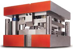
Protecting metal stamping dies
How to prevent die crashes with sensors
In most industries, improving process efficiency is an imperative part of product manufacturing. It is becoming increasingly important in metal stamping facilities throughout the world as competition requires that products to be made at a much faster rate and at a greater level of conformity.
The No. 1 reason for unexpected downtime or nonconforming parts in metal stamping applications is a die crash. Eliminating die crashes helps control repair processes and improves press time and production scheduling. A die that has been repaired after a crash also is unlikely to produce the same-quality product that it did previously.
The Role of Sensors
The best way to protect a die from damage is to make sure that nothing is physically out of place during a press cycle. This involves mounting a system of sensors in the tooling, connecting encoders to the crankshafts, and equipping the press with a controller to interpret the signals from these devices. Sensors verify processes and reduce the potential for die damage by detecting speed; accuracy; target orientation; and position, including part ejection and hole placement.
It is critical to protect die applications because of the stamping machine speed. Some stamping applications, like those for small electronic components, reach up to 1,500 strokes per minute (SPM); others, like those for large automotive frames or panels, run much more slowly at about 30 SPM.
At this rate, proper sensor placement and function are critical. Sensors often are placed in progressive dies at multiple locations for critical-point detection, such as bends, short feed, long feed, slugs, and missed hits.
Other types of stamping dies have specific requirements based on their function. For instance, in transfer dies, sensors are incorporated into the grippers to detect that panels are in place before they are transferred to the next station. Using sensors in these environments can reduce downtime and lost production, as well as associated maintenance costs and inadvertent shipping of bad parts.
Contact and Noncontact
The first thing to determine when incorporating sensors in a die protection application is the location and type of sensors needed to prevent damage. As previously mentioned, sensors can be used to make sure the material has moved forward in the application, to determine that the product has been ejected from the press, or to verify that the cams are in the correct position.
Sensors are available in contact and noncontact styles. Contact sensors are mechanical and must be physically touched for the output to activate. Noncontact sensors are electrical and use magnetic fields, light waves, or sound waves to determine position.
Contact sensors are less expensive than noncontact sensors, but they are subject to tremendous wear, which eventually leads to sensor failure. Noncontact sensors have a longer lifetime because they do not require contact, but they are more expensive.
Proximity Sensors
Proximity sensors are noncontact style and function by emitting a high-frequency electromagnetic field that interacts with a target (see Figure 1a and Figure 1b). When a metal object (target) enters the high-frequency field, eddy currents are induced on the surface of the target, and the sensor is affected by these currents.
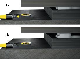
This sensor is programmed to measure the die's position. If slugs are deposited after the die stroke, the sensor will detect the difference in position.
Proximity sensors can be used in many places and for many functions within the die. The places and functions a sensor can be used for depends on the complexity and sophistication of the die, as well as the environmental conditions the sensor will endure, which include the material being sensed, the size of the target, the physical conditions near the die (weld fields, extreme heat or cold, RFI), and the electrical equipment to which the sensor will be connected (relays, programmable logic controllers, press controls, etc.).
Proximity sensors are solid-state with no moving parts and are impervious to oil, coolant, or other liquids and lubricants permeating the sensor. They have numerous housing styles that can be integrated in dies, such as miniature, rectangular, low-profile, and ring. For instance, flat pack proximity sensors can be embedded in the die to monitor the stripper plate to determine if slugs have been pulled into the die. A cylindrical proximity sensor can be placed in a spring-loaded lifter to detect whether the material has fed properly into position before the die closes.
Photoelectric Sensors
Photoelectric sensors, also noncontact style, use light (visible or infrared) to determine position or part ejection. These sensors include an emitter that sends out light and a receiver that measures the amount of light that returns to the sensor.
The three basic types of photoelectric sensors are:
- Through-beam—These usually consist of two separate housings for the emitter and receiver. When an object breaks the beam of light, a signal is sent to the controller.
- Diffuse-reflective—These send a signal to the controller when the light is reflected off of the part being sensed.
- Retro-reflective—These send a signal to the controller when the part interrupts the light being reflected back to the sensor via a reflector.
Like proximity sensors, photoelectric sensors are solid-state devices with no moving parts. While they offer much longer sensing ranges than typical proximity sensors, they are much more susceptible to fail in dirty environments when oil, dust, or other materials block the light to or from the sensor.
Controller Communication
No matter which type of sensor is used, the signals that are created must be sent back to a controller so it can take the appropriate action to protect the die. This is accomplished via wires and cables.
Some sensors have cable or wires running out of them that can be wired directly to the controller, while other sensors have connectors that allow quick wiring via a cable device called a cordset. Cordsets then are connected to a central junction box where the signal is routed to the controller via a "home run" cordset.
These cordsets and junction boxes are available in a variety of styles (field-wired, factory-molded, or a combination) that are designed to work in harsh manufacturing environments, although in many cases these components need to be further protected from scrap metal, forklifts, and other hazards. Some companies machine channels into the die shoe to protect the cable from damage, while others fill these channels with silicon rubber sealants or use conduit in the channel around the cable or wire.
Protecting Components
One of the most difficult problems to overcome in any die protection application is protecting the components from the environment in which they must function. In a typical stamping application, oils, coolants, and other liquids and lubricants often are present that can wreak havoc on the components.
Manufacturers of these devices have addressed this problem by making components out of higher-grade materials that are less affected by these substances and therefore classified with an ingress protection (IP) rating—the letters IP followed by two digits. The rating indicates the degree to which the enclosures of electrical components are sealed against the intrusion of foreign bodies such as dust and moisture.
This classification system was established by the International Electrotechnical Commission (IEC) to create uniform performance requirements for electronic enclosures intended for specific environments. Some sensors are designed for different levels of IP protection, making them more suitable for the harsh environments that often accompany die protection applications.
Manufacturers sometimes use alternative housing, connector, and front cap materials to make sensors more resistant. In general, as you invest more resources and components into your die protection system, the likelihood of failure or downtime is exponentially reduced.
Manufacturers demanding zero part defect or implementing just-in-time manufacturing often find that incorporating sensors into dies helps decrease downtime, part defects, and associated maintenance costs.
About the Author
About the Publication

subscribe now

The Fabricator is North America's leading magazine for the metal forming and fabricating industry. The magazine delivers the news, technical articles, and case histories that enable fabricators to do their jobs more efficiently. The Fabricator has served the industry since 1970.
start your free subscription- Stay connected from anywhere

Easily access valuable industry resources now with full access to the digital edition of The Fabricator.

Easily access valuable industry resources now with full access to the digital edition of The Welder.

Easily access valuable industry resources now with full access to the digital edition of The Tube and Pipe Journal.

Easily access valuable industry resources now with full access to the digital edition of The Fabricator en Español.
- Podcasting

In this episode of The Fabricator Podcast, Caleb Chamberlain, co-founder and CEO of OSH Cut, discusses his company’s...
- Trending Articles
1
AI, machine learning, and the future of metal fabrication

2
Employee ownership: The best way to ensure engagement

3
Dynamic Metal blossoms with each passing year

4
Steel industry reacts to Nucor’s new weekly published HRC price

5
Metal fabrication management: A guide for new supervisors
