


Graduate Research Associate - Center for Precision Forming

Formability is the ability of a sheet material to deform without failure or fracture. Information on formability helps process and tool design engineers predict failure during analysis of sheet metal forming processes for tool design. Formability information also is used to evaluate manufacturability of the designed part and for material selection based on complexity of part features and strength requirements.
In the sheet metal industry, the initial estimation of formability usually is based on total elongation, measured from the tensile test. Typically the larger the value of total elongation, the more formable the material. This inexpensive and simple way of evaluating formability, however, is not very reliable because while the tensile test is conducted under uniaxial conditions of stress and strain, the forming conditions in practical stamping operations are biaxial.
Therefore, most stamping engineers who use process simulation use a forming limit diagram (FLD), which represents the limits of fracture for a variety of stress and strain states, such as under uniaxial or biaxial deformation conditions. However, creating a single FLD for a specific material type and thickness requires a number of experiments and considerable time and expense.
Researchers at the Center for Precision Forming (CPF) of The Ohio State University propose using data from the uniaxial tensile test, biaxial bulge test, and FLD to estimate formability.
A typical engineering stress/strain curve obtained from a tensile test is shown in Figure 1. The most commonly used tensile data include yield strength, ultimate tensile strength (UTS), total elongation, and uniform elongation. While total elongation values indicate the formability of the tested material, uniform elongation is a more useful value since it does not include necking strain that occurs after the UTS stress.
The tensile data can be used to determine the true stress/true strain curve that is expressed, after curve fitting to the original stress/strain data, as:
σ = K εn
where:
σ = True stress
ε = True strain
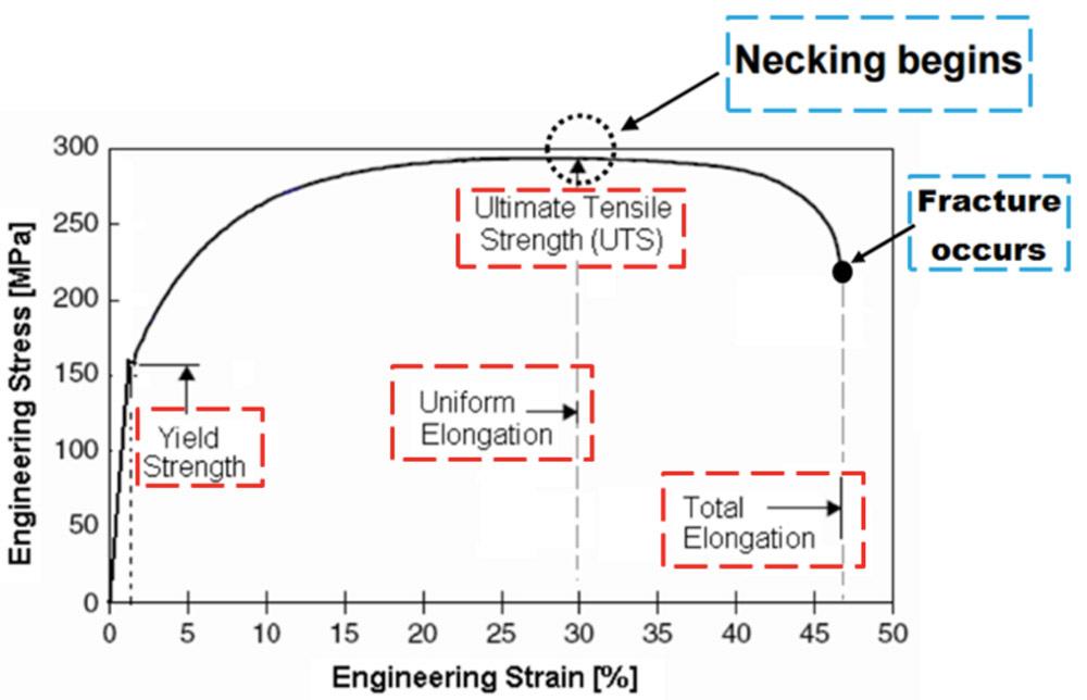
Figure 1
This typical engineering stress/strain curve was obtained from a tensile test.
K = Strength factor
n = Strain hardening coefficient
Because n can be shown to be equal to the value of uniform strain (see Figure 1), n often is assumed to be constant with varying strain and used as an indication of formability.
However, in advanced high-strength steels (AHSS), the value of n may vary with increasing strain, so its value might not be a good indicator of formability with those materials.
The bulge test emulates the deformation of sheet material under biaxial deformation conditions (see Figure 2). This test can measure the pressure and bulge height while the round blank is held at the flange with a lock bead to prevent metal flow toward the bulging material.
The formability of the tested material increases with the increasing bulge height at fracture.
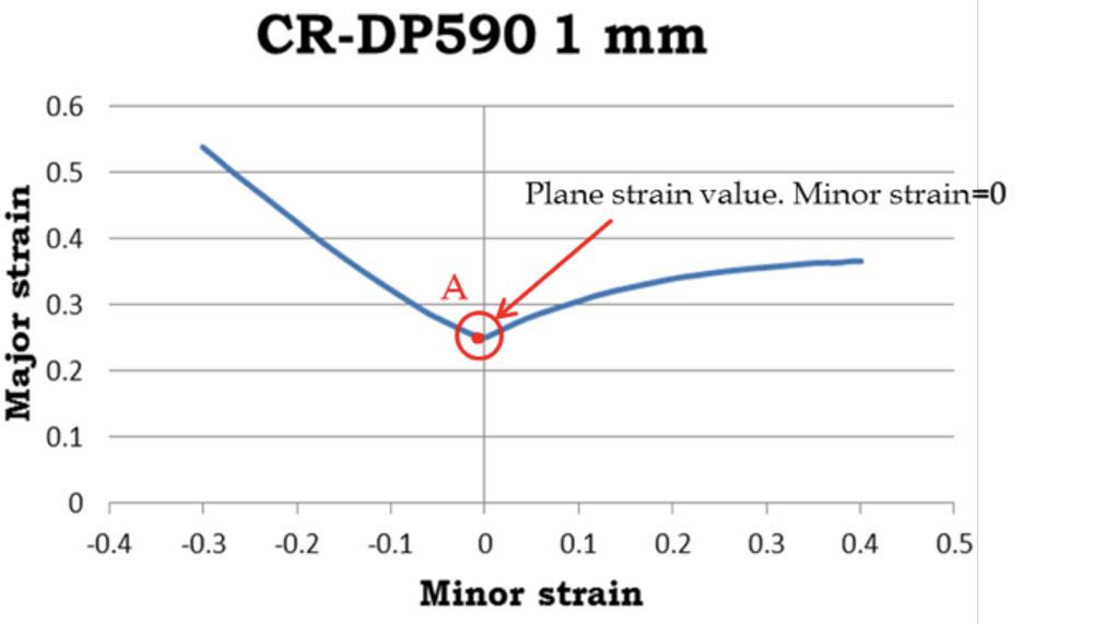
Most engineers who conduct process simulation using a commercial code, such as PAMSTAMP®, Autoform®, or LS-DYNA®, also use the FLD to predict fracture in forming a part (see Figure 3). In simulation, the strains can be calculated at any location in the part during deformation. Strains above the FLD curve indicate potential fracture.
While the FLD has been very useful in die and process design for low-carbon steels, it is not always reliable for AHSS. This is because FLD values vary with blank thickness, and also because they are obtained for one batch of material, even though material properties and formability can vary from batch to batch for the same material.
Furthermore, obtaining an FLD for a given material and thickness requires considerable time and cost. The FLD can be used to indicate formability, but it is not always reliable when applied to AHSS. Therefore, typical practice is to use percentage thinning to indicate potential fracture.
The lowest point in the FLD corresponds approximately to the plane strain condition, where the minor strain is close to zero. Thus, point A in Figure 3 also can be used as an indicator of formability. Considering the cost and time needed to obtain the FLD, it is reasonable to use the FLD data given by a material supplier for the same type of material with similar thickness and UTS.
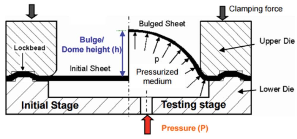
Figure 2
The bulge test is used to determine formability and the true stress/true strain curve.
The objective of the CPF study is to estimate formability of a given material type and thickness with as little effort and cost as possible. For this purpose, CPF suggests the use of:
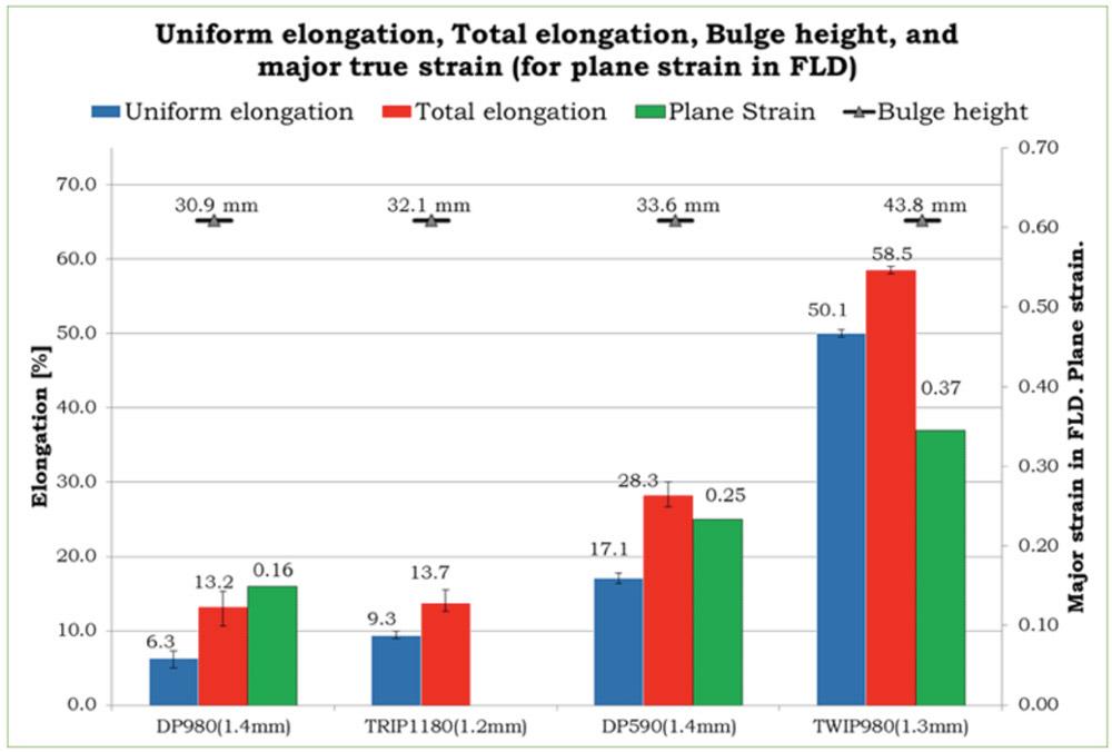
At CPF, formability data, as discussed previously, has been collected for a variety of AHSS: 1.4-mm DP980, CP800, and DP590; 1.3-mm TWIP980; 1.2-mm DP980 and TRIP1180; 1.1-mm TWIP900; and 1-mm DP780-HY, DP780, CR-DP780, TRIP780, and DP600. The formability of AHSS increases with decreasing UTS (see Figure 4). The UTS of the new TWIP and TRIP steels gives them relatively good formability.
Considering the inherent errors in measurements for most AHSS, this study has concluded that all the formability indicators show similar trends. While the FLD is not always reliable, it still appears to be the best indicator of formability. But since it is not easily available for each batch of sheet material, the tensile data and bulge test data provide useful indications of formability.
In stamping, local thinning is still a very good method for predicting fracture through simulation, although simulations may have some inaccuracies. It is desirable to evaluate, for a given material batch, the thinning at fracture with the available formability indicators. In practice, comparing thinning at fracture with the uniform elongation and total elongation obtained from a tensile test may be the easiest way to evaluate formability.
References
T. Altan et al., Sheet Metal Forming – Fundamentals, Vol. 1 (Materials Park, Ohio: ASM International).

Professor Emeritus and Director - Center for Precision Forming


The Fabricator is North America's leading magazine for the metal forming and fabricating industry. The magazine delivers the news, technical articles, and case histories that enable fabricators to do their jobs more efficiently. The Fabricator has served the industry since 1970.
start your free subscription
Easily access valuable industry resources now with full access to the digital edition of The Fabricator.

Easily access valuable industry resources now with full access to the digital edition of The Welder.

Easily access valuable industry resources now with full access to the digital edition of The Tube and Pipe Journal.

Easily access valuable industry resources now with full access to the digital edition of The Fabricator en Español.
In this episode of The Fabricator Podcast, Caleb Chamberlain, co-founder and CEO of OSH Cut, discusses his company’s...


