


Graduate Research Associate - Center for Precision Forming
In deep drawing, with or without draw beads, the sheet metal blank is restrained at the periphery of the die by the blank holder force (BHF). The relative motion between the punch and the die forces the metal to flow into the die cavity (see Figure 1). The quality of the formed part is determined by the amount of material drawn into the die cavity. Excessive metal flow may cause wrinkling, while insufficient metal flow will cause excessive thinning and fracture in the drawn part.
Metal flow into the die cavity is controlled primarily by the BHF (see Figure 2). If spacers (distance blocks) are used between the die and blank holder, the thickness of the spacers also regulates the material flow. Spacer thickness generally is adjusted during die tryout, and this process can require considerable knowledge, experience, and time. However, Audi developed a laser- and servomotor-based system that controls spacer height during production, from one stroke to the next, to help simplify this process (see STAMPING Journal®, May/June 2016, p. 16).
When forming without spacers, the BHF can be controlled during the press stroke using a hydraulic cushion. With servo control, the cushion force can be varied during the stroke. Thus, the BHF can be varied to obtain the optimum metal flow control, based on part geometry and sheet material thickness and properties.
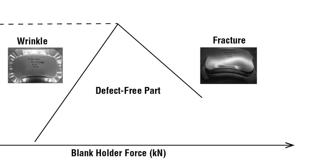
As an example, the effect of constant BHF upon part quality and achievable draw depth is illustrated in Figure 2. When the BHF, assumed to be constant throughout the stroke in this example, is too large, the drawn part will fracture or tear. When the BHF is too small, wrinkles can occur in the flange and sometimes on the part wall.
Servo hydraulic cushions allow the operator to change the BHF during the press stroke, within the limits of the specific inertia of the hydraulic system. This level of accuracy is made possible by the closed-loop control inherent in servo hydraulic cushion systems. Linear position, pressure, and temperature are monitored constantly and fed back to the controller and servo valve.
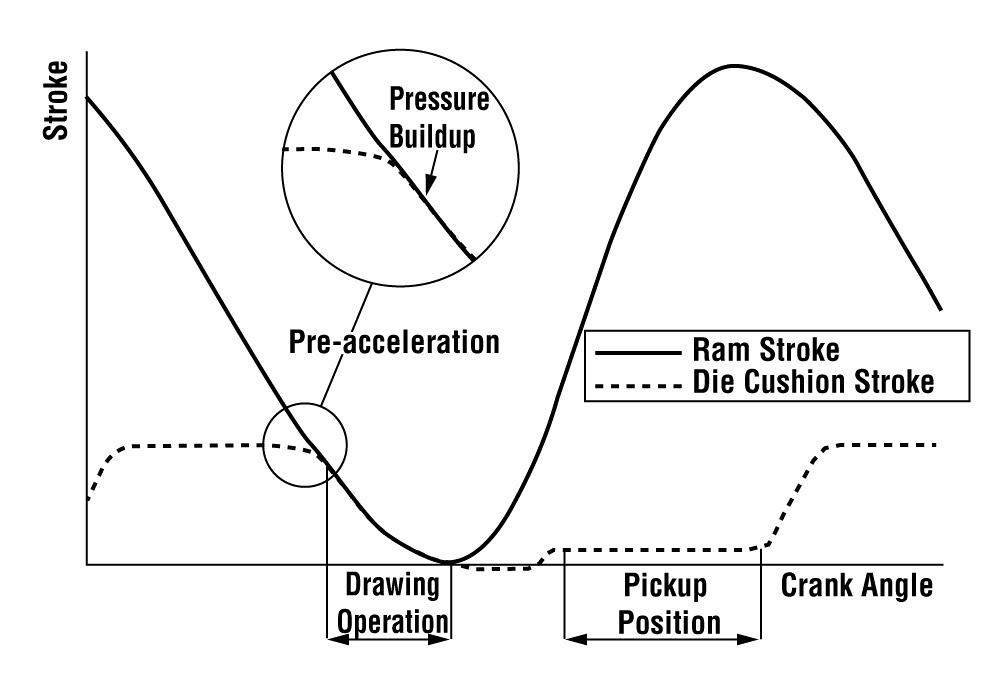
The cushion can be accelerated in the direction of the die motion just before the die hits the blank (see Figure 3). This decreases the relative velocity between the die and the blank holder, eliminating sudden shock on the press, tooling, and blank and reducing press maintenance and lubrication problems.
After the forming operation, the return motion of the die cushion can be delayed at bottom dead center to prevent back-to-back contact of the blank holder with the formed part (see Figure 3).
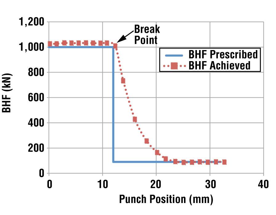
When spacers are not used, with a servo hydraulic cushion the BHF can be varied during the press stroke to obtain the desired metal flow. Often it is not easy to select the BHF curve versus stroke to avoid part failure because of fracturing or wrinkling. As seen in Figure 4, it can be done either from experience during die tryout or using a computer simulation.
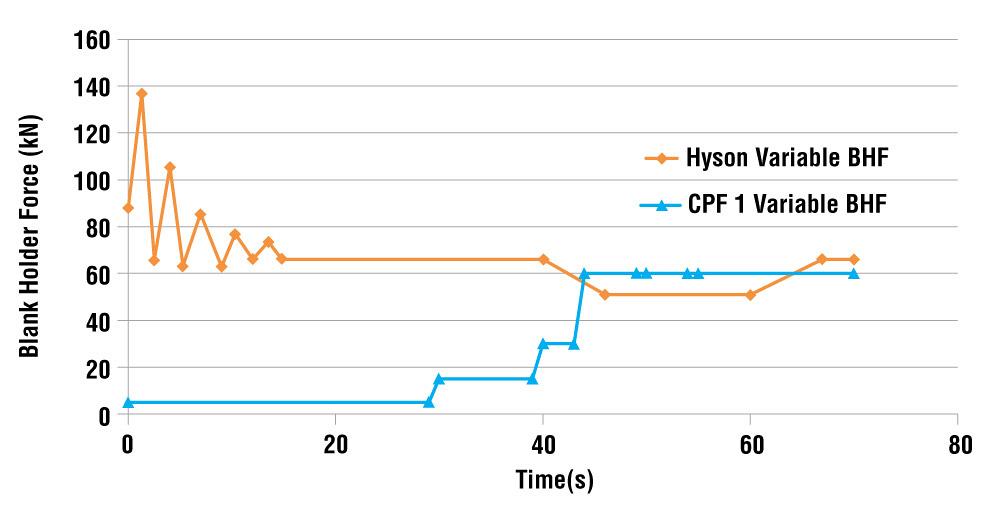
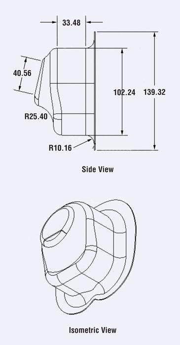
In a study conducted jointly by the Center for Precision Forming and HYSON Metal Forming Solutions™, a stainless steel part was formed successfully in a servo press using BHF that was variable during the press stroke (see Figure 5).
The stretching, and thus strain hardening and dent resistance, of exterior autobody panels can be improved by increasing the BHF at the start of deformation (see Figure 6).
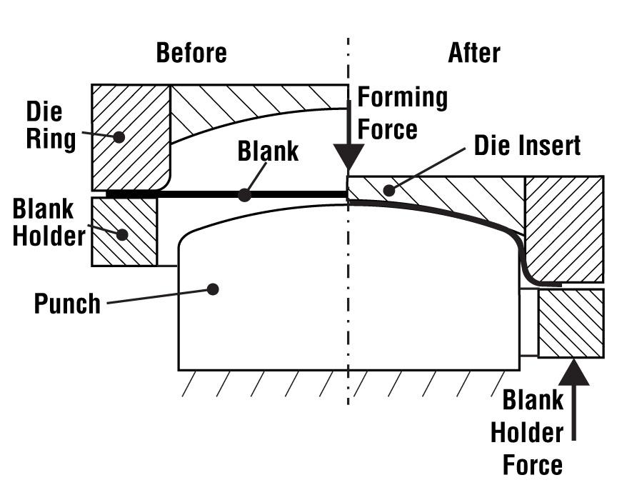
Figure 1
In this deep-drawing tooling, the BHF is
provided by a cushion (no spacers).
Similarly, by increasing the BHF toward the end of deformation, it is possible to reduce springback and increase the straightness in the wall of drawn parts.
Research in drawing using low-frequency BHF vibrations (10 to 50 hertz) showed that it is possible to reduce thinning and fracturing during deep drawing. Vibrations reduce friction and heat buildup in the flange, as the blank slides under BHF and pressure. As a result, the achievable draw depth can be increased.
The practical application of this technique, however, requires additional tryouts and experimentation to ensure that it does not reduce cycle time and productivity in deep drawing certain difficult-to-form materials.
The mechanical properties of most advanced high-strength steels (AHSSs) vary from coil to coil or batch to batch. When forming without spacers, it is possible to adjust the BHF using a servo hydraulic cushion to compensate for these variations and maintain formed part quality.
Draw beads are used extensively to form low-strength alloys. In such applications, nitrogen cylinders or air cushions are used to generate the BHF or the force applied to the spacers. As the use of AHSS increases, the shape of the draw beads is modified to reduce the amount of strain hardening.
When deep drawing without draw beads, relatively large BHF or cushion pressure is required. In some cases, the use of servo hydraulic cushions may help to eliminate draw beads and spacers. The result is a reduced amount of trimmed flange, as well as material savings.

Professor Emeritus and Director - Center for Precision Forming


The Fabricator is North America's leading magazine for the metal forming and fabricating industry. The magazine delivers the news, technical articles, and case histories that enable fabricators to do their jobs more efficiently. The Fabricator has served the industry since 1970.
start your free subscription
Easily access valuable industry resources now with full access to the digital edition of The Fabricator.

Easily access valuable industry resources now with full access to the digital edition of The Welder.

Easily access valuable industry resources now with full access to the digital edition of The Tube and Pipe Journal.

Easily access valuable industry resources now with full access to the digital edition of The Fabricator en Español.
In this episode of The Fabricator Podcast, Caleb Chamberlain, co-founder and CEO of OSH Cut, discusses his company’s...


