


Contributing Writer
During the past five years, the process of draw die development has undergone significant changes as a result of technological improvements and the demand for higher-quality products.
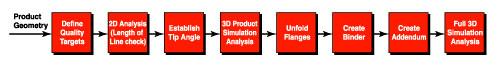
Figure 1:
The eight steps in the advanced draw development process are designed to identify and address problems before dies are built.
Traditionally, draw die development was perceived as an art; development processes were created based on a draw development engineer's expertise or experience with similar models. This approach generated many differing opinions on the design of a draw development and lacked a consistent link to the quality requirements of an assembled product. A draw development was considered successful if it literally could hold water—if it contained no splits. This method of evaluation resulted in quality levels that were limited by the experience of the draw development engineer.
When an engineer encountered a panel that was unfamiliar or complex, many formability concerns went unanswered. In many cases, even if the development engineer had alternative draw development ideas, they were difficult to prove out because testing possible solutions was expensive and time-consuming. Also, the trial-and-error method of tryout left little time for tackling new ideas without a clear direction.
In this process, the forming severity and quality level of the development were not tested until the soft-tool stage.
Today's customers are more sophisticated, and they can detect variations in the fit and finish of a vehicle, differences that went unnoticed on earlier models. This fact, along with a growing cost awareness, brought pressure on the marketplace to streamline stamping processes and manufacture higher-quality products at lower costs. To meet this challenge, OEMs are using technology and benchmarks to closely monitor both the surface quality of vehicle components and the processing methods used to produce them
.These new requirements have forced many companies to adopt an integrated and advanced approach to draw die development. In this new process, the objectives for a draw development are established through simultaneous engineering, during which cross-functional teams work together to ensure an understanding of one another's targets.
The established objectives take into consideration product, manufacturing, and assembly requirements, and they are often linked integrally. Using metal forming simulation tools during the product and draw development stages, the teams verify that these objectives are practical. This advanced analysis accelerates the draw development process by eliminating unfeasible geometries before the draw development process begins.
This article summarizes the eight steps involved in this advanced draw development process (see Figure 1).
As mentioned previously, some quality targets for a draw development are based on the requirements of the finished product. These targets are determined by the vehicle design, product, manufacturing, and cost objectives. For example, common quality and cost targets for outer panels include:
1. Protecting them from dents and dings with a minor stretch of at least 1 percent on exposed surfaces.
2. Providing crisp feature lines with balanced tension forces to prevent skid-line movement.
3. Adding overcrown to reduce the potential for highs or lows on exposed surfaces.
4. Ensuring good surface reflectivity that meets design intent.
5. Avoiding wrinkles on weld, seal, or hemming surfaces.
6. Ensuring consistent gaps on all cut lines.
7. Controlling thin-out to produce safe parts.
8. Reducing the number of dies required and minimizing extra operations necessitated by specific product requirements.
9. Minimizing material usage of the draw development.
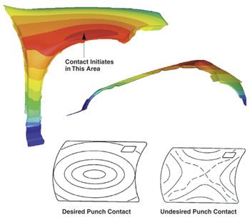 |
| Figure 2: Checking the tip angle and punch contact with metal forming simulation software ensures that the material's ability to stretch over the punch is not inhibited. |
With sections cut through the product geometry, a comparison of the original material length to the final product length (length-of-line check) is performed to ensure that the geometry is within acceptable limits. This is a conservative analysis because it is based on a stretch condition (a simulation tool is required for complex geometries).
By using this analysis, development engineers can predict a product's problems with severe stepped geometry or tight radii early in the product definition stage.
Next, a metal forming simulation tool is used to check the tip angle and punch contact of the product geometry (see Figure 2). Although the tip angle is restricted by the process line-up, an evaluation is made at this point to ensure that the process line-up has not limited the ability of the material to stretch over the punch.
When forming outer panels, it is important that the punch contact initiate from the center of a panel and progress outward. However, punch contact should not be too large because lower strain values caused by material sticking to the punch surface may result.
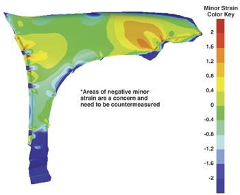 |
| Figure 3: A 3-D analysis of product geometry can identify potential problems that can be addressed during the product development stage. |
With a metal forming simulation tool, an analysis of the product geometry is performed to determine if the established quality targets are attainable. During this process, a simulation engineer evaluates the part by adding a restricting force around the perimeter and attempting to achieve the desired strain level while eliminating defects such as wrinkles and highs or lows.
Because this step occurs during the product development stage, the goal is to identify potential problems and determine countermeasures for them (seeFigure 3). As shown in Figure 3, the panel has areas of negative strain on the exposed surface. These areas would be evaluated for possible countermeasures, which could involve a product change or may be addressed later during the draw development stage.
If the product analysis proves that the quality goals are unattainable given the product geometry, product engineering concessions are more likely at this early stage in the build cycle. If the product analysis indicates that the quality goals are reasonable, the draw development process can begin.
Identifying potential defects in product geometry and correcting them before building the draw development save time and money for both the supplier and the customer.
The next step in the draw development process is to unfold or lay out the flanges. This must be done to facilitate the panel process line-up and to accommodate trimming or flanging guidelines. If possible, direct trimming or flanging is preferred rather than using cams for such operations. If hemming is required, steps must be taken to ensure that panel quality is not sacrificed during the hemming process.
Because the tip angle and punch contact were established in Step 3, the process of defining the binder shape can begin.The binder shape for outer panels is created from the shape of the initial punch contact. This prevents material sag and is likely to provide the best opportunity for achieving the desired strains.
Creating the binder shape for inner panels is more complicated because more severe geometry transitions must be considered. In addition, the amount of inner form on most inner panels may necessitate designing a longer length of line in the die cavity. To avoid creating a binder surface that raises formability or quality concerns, a metal forming simulation tool should be used to verify the binder wrap and the potential for defects attributable to the binder shape.
With an understanding of the restraints established in Step 3 and the quality goals that were achieved, the draw development engineer creates the addendum to connect the unfolded flanges to the binder surface. In this process, the need for a specified draw depth, drawbars, gainers, etc., must be considered to ensure restraints similar to the product analysis.
At this stage, the draw development engineer must be familiar with various addenda that can be used to ensure that drawing principles, such as balancing the length of line in neighboring areas of the panel, are followed. This is common with a door inner because of the difference in length of line at the beltline. This difference can be equalized by using a drawbar around the window frame opening to reduce the potential for wrinkling in the transition area (seal or hemming surface area).
Addenda also can be designed in the draw die to assist in the forming of a part in later operations. This occurs with a stretch flange, for which extra material is provided to reduce the severity of a secondary flanging operation.
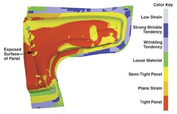 | |
| Figure 4: When all considerations have been factored into the draw die development, a full 3-D simulation can be performed to gauge whether the draw development meets all quality targets. |
After the draw development engineer has completed a final review to ensure that the established quality, panel processing, and material use have been considered in the creation of the draw development, a full 3-D simulation can be performed (see Figure 4). This analysis focuses on reproducing the tryout of a die. All input parameters are simulated under production conditions to ensure reasonable accuracy. The success of a draw development is based on meeting the quality targets established in Step 1.
After a simulation review is completed and the cross-functional teams are satisfied with the quality targets achieved, a simulation report is created for the tool build source. This includes all critical information such as the draw bead shape, edge movement, material properties, and press setup conditions.
With the advanced draw development approach, the quality of a product is tested earlier in the build cycle, before the draw development process begins. Countermeasures for difficult forming areas also are addressed before the draw development process begins.
The draw die development uses the experience of a draw development engineer but has the quality expectations designed into the process. As a result, the draw die development provides a higher level of confidence at the time of the hard-tool tryout and has the potential to eliminate soft tools, reduce tool build lead time, and lower total tooling costs.


The Fabricator is North America's leading magazine for the metal forming and fabricating industry. The magazine delivers the news, technical articles, and case histories that enable fabricators to do their jobs more efficiently. The Fabricator has served the industry since 1970.
start your free subscription
Easily access valuable industry resources now with full access to the digital edition of The Fabricator.

Easily access valuable industry resources now with full access to the digital edition of The Welder.

Easily access valuable industry resources now with full access to the digital edition of The Tube and Pipe Journal.

Easily access valuable industry resources now with full access to the digital edition of The Fabricator en Español.
In this episode of The Fabricator Podcast, Caleb Chamberlain, co-founder and CEO of OSH Cut, discusses his company’s...


