


Contributing Writer
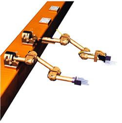 |
| Figure 1: Tooling is mounted to transfer rails by receivers, which provide mechanical, electrical, and pneumatic connections. |
Improvements in transfer press automation and the availability of used large-bed presses for retrofitting have accelerated the use of transfer presses with their in-press automation and transfer fingers that move work-in-progress (WIP) between a series of dies in one press.
If transfer press automation fits your production needs, the next question is, what kind of tooling do you need?
Traditionally, finger tooling for transfer presses has been fabricated from tubing and brackets after die design. Creating a set of finger tooling can be labor-intensive because each finger must be developed to achieve the proper angle and position, then cut and machined or welded. No standard components have been available, which has made the tooling costly because it was all custom-made.
Furthermore, miscalculations or changes have meant time-consuming, potentially costly rework because dedicated tooling usually has not been easily adjustable. In some cases, dies have needed to be redesigned and remachined to accommodate finger entry. If a die crash occurred during production, damaging the tooling, downtime could be lengthy while hard tooling components were reworked or refabricated.
Another option now available for use with transfer presses is adjustable articulated finger tooling (see Figure 1). Adjustable tooling typically is a modular system of standard-length tubes (arms) and joints that make up the fingers.
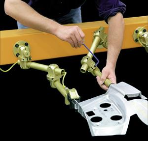 |
| Figure 2: Articulated finger tooling can be assembled from standardized components and allows rotational and linear adjustment. |
The tooling consists of fingers that are mounted to a transfer rail by receivers that allow space for mechanical, electrical, and pneumatic connections (see Figure 2). The transfer rail is moved by mechanical or servo-driven automation that achieves the clamp, lift, transfer, unclamp, and return strokes. Rotational and linear adjustments of the fingers are possible, which allows shovels or grippers to be aligned for the various angles encountered along the edges of contoured stamped parts.
Standard bases can be used to bolt finger tooling directly to transfer rails for applications in which the finger tooling is stored with the rails when they are not in use. In these applications, rails are replaced, complete with tooling, for each part number to simplify and speed part changeover.
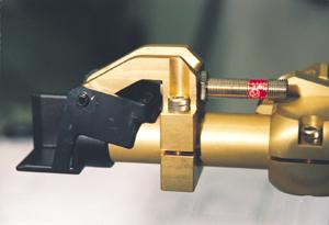
Receiver-style housings, on the other hand, feature quick disconnects that allow the removal and replacement of individual fingers on a rail. Because it is not fastened directly to the rail like the standard base, the quick disconnect is equipped with attachments for air and electrical connections to accommodate sensors and grippers. Maintenance and replacement of individual fingers can be accomplished more quickly with this receiver arrangement.
Quick-connect features enable fast setup times that match today's quick die change requirements. Trial-and-error setup times can be reduced because standard components allow tooling to be set up quickly and reconfigured easily. Adjustability in three axes allows angled approach paths to a part to be set and reset, and the end effector also can be rotated.
Adjustable tooling can be designed in about a half day and built in less than two days. To minimize costs and ease setup and maintenance when designing or selecting finger tooling, specific attributes are important. Tooling should be:
When designing or setting up individual finger tools, using common "0" datums for dimensioning helps to ensure accuracy. The datums are:
In terms of part contact, the datums include the:
The single most important concern when applying in-press transfer tooling is maintaining part control. Correct positioning of parts and controlling them as they are transferred from die to die are essential for preventing downtime and scrap and for achieving maximum transfer press production speeds.
Parts must be in position before transfer fingers are in the clamp position. Flimsy parts that tend to catch air and those that lack sharply defined corners are not good candidates for transfer applications because of difficulties that can arise in positively controlling part location. Parts with very deep draws also are poor choices for production on transfer presses because allowing sufficient room for lift and transfer is difficult.
 |
| Figure 3: Shovels can be attached to fingers to support parts during transfer. |
Shovels. Shovels are used to support a part during transfer (see Figure 3). The most effective shovels are those that fit the part shape as closely as possible. Ideally, a part should be captured and held during all three axes of motion.
Many times, an additional piece is welded over the top of a shovel to prevent a part from bouncing. This can be effective for transferring a part, but it sometimes can cause problems when the transfer stops or when a need arises to remove a part from the shovels because of a jam, quality checks, or machine cleaning.
Shovels usually are made from steel and are either cast or stamped, although aluminum is used sometimes if higher strength-to-weight ratios are required. Stamped shovels are the most common type used today. Most are produced from 1018 steel, and they can be modified by welding, cutting, or bending. However, when setup personnel and press operators alter a shovel from the shape for which it was originally engineered, its life and strength may be reduced greatly.
Cast shovels provide additional rigidity to transfer heavier parts without losing their shapes. Their main drawback is that they cannot be altered.
Grippers. Grippers may be needed to prevent a part from bouncing when the die opens or to control one that catches air and waffles during transfer. Grippers also can be used when part shape precludes the use of shovels, when very little material is available for capture, or when the blank shape results in unbalanced weight.
Using grippers lessens the chance of losing control of a part, which can improve the speed of transferring flimsy parts in some applications even though additional time is needed to close and open the gripper.
There are several options for mounting grippers. When no horizontal adjustment is needed, a bracket that attaches to the gripper and the tooling arm can be used. Other brackets incorporate a universal ball joint to allow final location adjustment for a horizontal approach to the part.
A growing movement is afoot to standardize the use of grippers. The initial cost for grippers is higher, but many believe that the long-term cost is less because increased part control helps to eliminate costly downtime.
 |
| Figure 4: An edge sensor uses a flipper gauge to determine when a part enters a shovel. |
Part-presence sensors can help to prevent damage to dies and transfer tooling when part control is lost or when mishaps cause parts to come out of dies. Sensors can detect either the edge of a part or the part's surface. They must be designed to survive in extreme environments characterized by contamination from lubricants, cutting oils, and coolants; high pressure and temperature variations; and vibration.
Inductive proximity switches, which can be either AC- or DC-powered, are the most widely used type of surface sensor. The most effective sensors of this kind have small envelopes but large sensing ranges. Photoelectric sensors also have large sensing ranges, but they are more sensitive to contamination by drawing compounds, oils, or dirt.
Sensors always must be positioned properly to sense part presence. Locating them properly often depends on the die design and part-sensing requirements. It is common to mount or install sensors at the shovel or gripper. However, when there is not enough room to do so, the sensor can be mounted by an extension bracket attached to the tooling arm.
Sensors on Shovels. Sensors also can be mounted flush with the shovel bottom and attached either on a bracket directly to one side or below. To mount a sensor below the shovel bottom, a hole is pierced through the bottom of the shovel, and a bracket and sensor are mounted underneath. This allows sensing of the part when it enters and is captured by the shovel. The drawback to this type of mounting is that additional space is needed below the shovel.
These sensors have a limited range and are not always effective if a part bounces or does not seat itself completely inside the shovel. An effective range for a sensor of this type is 1⁄4 to 3⁄8 in., which is difficult to achieve while maintaining a small envelope.
An edge sensor assembly also is available (see Figure 4). The assembly is bracket-mounted to the tooling arm and shovel and operates with a flipper gauge, a stamped component that straddles the shovel and is attached to the bracket with a roll pin. When the part enters the shovel, it pushes the flipper back, rotating the other end up and activating the sensor. Part bouncing does not affect the sensing range because the flipper is fixed on the roll pin. When the gauge is pushed back, it always rotates up into the same position to activate the sensor.
In-die Sensors. In-die sensors offer an alternative to sensors mounted on the tooling arm. They usually incorporate the same types of sensing devices, including inductive proximity and photoelectric sensors.
These sensors can be used either under the part in the die to confirm part presence, or they can be mounted just beyond the die station to sense the part as it leaves during transfer. This often is called a part-leaving sensor.
All dies must be designed to locate a part positively. Methods for accomplishing this include the use of pilot pins, trim tabs, and high gauges. To load a part on the lifter in the up position, high die-mounted pilot pins are required.
When there is not enough clearance for a finger to reach under a part, it is necessary to lift the part to a level at which the fingers can capture it. Lifter travel should be kept to a minimum to save time and to lessen the possibility of part bouncing.
All direct lifters should be ram-controlled, which means that they are controlled by the upper die member. One option is to use lifters that are controlled by the press processor. Processor-controlled lifters are timed to fire at the bottom of the press stroke. The lifter then is controlled by the pad or ram through the upstroke.
A lifter should be as flat as possible to facilitate easy part removal and sized to fit the part surface it contacts to prevent shifting during the lifting action. In some cases, the use of stop blocks or gauges may be required to prevent a part from sliding.
Die conditions and the flatness of a part (the lack of appropriate part shape) may cause it to shift off the gauge on the lifter upstroke. If this is a problem, vacuum cups can be mounted to the lifter assembly to aid part control.
An interference curve shows the path of the tooling fingers in relation to the die members at any point in time during the press stroke. During die design, a template of the finger and rail travel is used to ensure that the die features do not collide with the transfer mechanism.
Mechanical drive transfers have only one interference curve, which is used for every part. When the transfer is servo-driven, there are different curves for each part because setup parameters are adjustable and thus variable, including the distance between the transfer rails and the amount of clamp, lift, and transfer.
Because the ram of the transfer press is in motion continuously during part transfer, potential interference between the press and the transfer tooling during the transfer cycle must be avoided. Interference can occur between:
During die design, special attention should be given to the amount of vertical lift that occurs before the start of the horizontal motion. When there is a limited amount of vertical lift before the horizontal motion starts, an arc is created that also could present a clearance problem.
Looking to the future, the practice of presetting articulated finger tooling may further reduce downtime and therefore costs. Setup fixtures will allow settings developed from traditional trial-and-error adjustments or from die designs or simulations to be recorded and used later. Preset, prefabricated tooling will be able to replicate finger adjustments for maintenance purposes or when fingers need to be re-created after damage has occurred. Offline simulation also will be possible.
Transfer press operators have numerous factors to consider before deciding on a tooling strategy that allows the system to work as efficiently as possible. Regardless of the application, evaluating the part, the process, die design, and finger tooling type and design—simultaneously, if possible—is important to help ensure transfer press success and efficient stamping production.


The Fabricator is North America's leading magazine for the metal forming and fabricating industry. The magazine delivers the news, technical articles, and case histories that enable fabricators to do their jobs more efficiently. The Fabricator has served the industry since 1970.
start your free subscription
Easily access valuable industry resources now with full access to the digital edition of The Fabricator.

Easily access valuable industry resources now with full access to the digital edition of The Welder.

Easily access valuable industry resources now with full access to the digital edition of The Tube and Pipe Journal.

Easily access valuable industry resources now with full access to the digital edition of The Fabricator en Español.
In this episode of The Fabricator Podcast, Caleb Chamberlain, co-founder and CEO of OSH Cut, discusses his company’s...


