


President
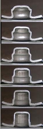
Figure 1: The contact angle between the previous workpiece and die radius in sequence drawing should be within 45 degrees to prevent shock lines and subsequent cracking.
Drawn parts with very precise circularity, roundness, and straightness, as well as no score marks, are in strong demand in the automotive, medical, and electronics industries. Cylindrical parts that used to be produced by machining or grinding now are being produced more frequently with sheet metal deep drawing for improved productivity and reduced costs.
In the production of a drawn cup, the workpiece diameter is reduced gradually, step by step. A previous workpiece touches the die-lip of the next drawing stage, and it is pulled into the die mouth.
Until recently there has been no clear standard for this contact angle. When the contact angle is too large, the portion of the first tool touch is expanded to the outside, and a shock line appears inside the drawn part. Mild material can assimilate these faults by the end of the deep-drawing stroke, but if the material is too hard, a crack will form at the shock line (see Figure 1).
To prevent such problems, 45 degrees has been chosen as an approximate standard contact angle to be tested (see Figure 2). It is considered suitable for normal-quality drawn cups.
The material of the contact portion expands outward during this process. Even if the contact angle is less than 45 degrees when the cup round of the workpiece touches the die radius, the contact angle becomes far larger than 45 degrees when the vertical wall of the workpiece passes through the die radius a moment later (see Figure 3).
A small swell grows at the die radius as the flow stagnates. The swelling tends to be unnoticeable because it doesn’t appear when processing is complete, but if the swell is not the same size all around, it can cause several problems:
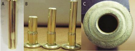
*Score marks—If swelling occurs when the material is drawn into the perpendicular wall of the die, a portion of the material can be scraped off, causing roughness in the surface (see Figure 4A).
*Curved drawn parts—The size of gap A is different from gap B because the swell pushes the cup wall (see Figure 3). The unbalanced resistance force during processing causes a curve in the middle of the finished part (see Figure 4B).
*Unbalanced flange lip roundness—With swelling, the wall thickness distribution of the vertical drawn cup is not uniform along the circumference. When parts curve this way in the middle of processing, a flange-lip bias occurs (see Figure 4C).
When these malfunctions happen, the workpiece typically suffers from a wall break, and galling appears on the die lip. As a result, the finished product is defective because of imprecise roundness and straightness.
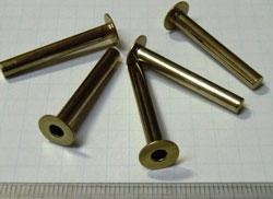
Figure 7: These precise cylindrical parts were deep-drawn with a 15-degree conic lip die and an added intermediate process.
A die with a conic lip of 15 degrees can be used in drawing to prevent swelling when the workpiece’s vertical wall passes through the lip (see Figure 5). This conic lip is very effective for preventing the swelling and can eliminate almost all of the resulting problems. As a whole, the drawing force decreases while the life of the die increases.
While the 15-degree conic lip is good for preventing swelling, it causes a 15-degree neck under the flange in the workpiece, which is not acceptable for the final product.
When a very small neck is needed for the final product and this small radius is used in the final drawing die, the small die radius shaves off a portion of the cone, causing severe galling. Adding an intermediate process with a large-radius die will push the cone out to the flange in the final process to prevent galling (see Figure 6).
Figure 7 shows precise cylindrical parts deep-drawn with a 15-degree conic lip die and the added intermediate process. Made of 0.02-in.-thick C2680 material, the part is 1.19 in. long with a straightness of 0.0004 in. Outer diameter is 0.16 in. and inner diameter is 0.14 in., with roundness of 0.0004 in. and a neck round of 0.006 in.
This type of precision drawing work can be achieved by paying attention to the contact point of the drawing die with the workpiece and using a contact angle between 15 and 45 degrees. While an angle smaller than 15 degrees is preferable, the parabola shape sometimes is applied as a die lip, and it’s not easy to make this shape or to confirm its accuracy.Taking a proactive approach during the process is key to precision results.


The Fabricator is North America's leading magazine for the metal forming and fabricating industry. The magazine delivers the news, technical articles, and case histories that enable fabricators to do their jobs more efficiently. The Fabricator has served the industry since 1970.
start your free subscription
Easily access valuable industry resources now with full access to the digital edition of The Fabricator.

Easily access valuable industry resources now with full access to the digital edition of The Welder.

Easily access valuable industry resources now with full access to the digital edition of The Tube and Pipe Journal.

Easily access valuable industry resources now with full access to the digital edition of The Fabricator en Español.
In this episode of The Fabricator Podcast, Caleb Chamberlain, co-founder and CEO of OSH Cut, discusses his company’s...


