


Professor Emeritus and Director - Center for Precision Forming
Editor's Note: This column was prepared by the staff of the Engineering Research Center for Net Shape Manufacturing (ERC/ NSM), The Ohio State University, Professor Taylan Altan, director.
Binder, or blank holder, force control is an important variable in the stamping process. Constant blank holder force (BHF) is applied throughout the stroke at all binder locations by using nitrogen cylinders, hydraulic cylinders, or pneumatic cushions. To increase the formability of stamped parts—that is, producing fracture- and wrinkle-free parts—BHF variation in stroke and location is essential.
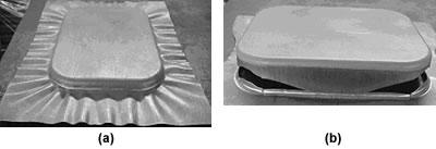 |
| Figure 1 Low BHF can result in wrinkled parts (a), and unnecessarily high BHF can result in fractured parts (b). Source: ERC/NSM. |
Research is ongoing at companies, universities, and institutions around the world to predict BHF profiles to optimize process variables in stamping. Low BHF can result in wrinkling, and high BHF can result in fracturing (see Figures 1a, 1b).
Figure 2shows a press and tooling with programmable displacement cylinders designed to vary BHF, but even with such a design, the question remains, How do stampers determine the correct variation of BHF in location and in time during the press stroke and program each cushion pin? To answer this question, the ERC/NSM is developing a BHF software package. Currently BHF profiles are determined by trial and error or are not done at all because it takes too much time.
 |
| Figure 2 Presses and tooling with programmable displacement cylinders are designed to vary BHF during the press stroke at various binder locations.Source: Schuler Inc. |
The software for determining an optimum BHF variation requires a systematic approach. Required input parameters for BHF software along with CAD data include material properties, process conditions, quality control parameters such as wrinkling and thinning, number of cushion pins, and part forming depth. By using BHF software, stampers might be able to reduce die tryout and computation time.
Figure 3shows an automotive body panel formed with 15 independent cushion pins. Depending on the corners or panel sides, several of these hydraulic cushion pins must be activated and programmed differently to obtain maximum formability. Each activated pin applies a different level of force and pressure on the specific area of the binder. As a result, material flow is directed such that thinning and wrinkling are reduced.
Nitrogen cylinders that provide an initial resistance, or tonnage, at the top of the stroke often undergo an increase in tonnage as gas in the cylinders is compressed. This is commonly known as pressure rise. Some manifold systems exhibit a 5 to 10 percent pressure rise, while self-contained gas springs have a 10 to 30 percent pressure rise throughout the stroke.
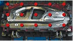 |
| Figure 3 This automotive body panel is manufactured with 15 cushion pins. Depending on the corners or panel sides, each hydraulic cushion pin must be programmed differently to obtain maximum formability. Source: Muller Weingarten. |
In addition, nitrogen cylinders provide maximum resistance when the press and the binder ring collide (impact shock), and the uncontrolled return of the cylinders may cause a second shock to the press during the return (return shock, draw ring bounce, or backslap).
Repetitive impact shock can damage a press and the dies. Poor tonnage control encourages part buckling early in the stroke and tearing late in the stroke. As a result, part quality may be reduced, and scrap rates may be increased. Shock vibration destabilizes parts during transfer, and the desire for stable part transfer and better part forming often leads to press and press line slowdowns.
When part quality issues surface, a common response is to shut down the press or press line until the problem is resolved. The same is true with press damage. The aggregate impact is felt on the bottom line, and the dollars involved can be substantial. On large stamped parts and in large-volume operations, these problems may produce significant losses per year, per part.
Solutions to Improve Binder Ring Control
Several companies, such as Schuler Inc., Muller Weingarten Corp., and Red Stag Engineering & Automation, supply multiple-point hydraulic cushions with individually programmable hydraulic cushion pins (see Figures 2, 3). These hydraulic cushions also can be programmed to preaccelerate the cushion, so the difference in speed between the upper and lower binder plates is reduced. The return binder stroke can be programmed, which eliminates shock impact on the binder during down-and upstrokes.
Another solution, called the Force Modulator™, is offered by Metal Forming Controls Corp. This system was created to reduce shock and control tonnage during the press stroke. The system functions like a press cushion and can be integrated into a die. It consists of a set of hydraulic cylinders. Each cylinder has a proprietary control device that allows resistance (tonnage) control at all points in the cylinder's stroke.
Low tonnage can be used to generate a soft hit on the downstroke, high tonnage can be used to set the bead, followed by lower or higher tonnage anywhere in the stroke to manage the flow of metal into the part. At the bottom of the stroke, the system can hold at the bottom upon receipt of a signal from the press or can provide a soft return. All equipment in the system, including a pump, accumulator, and a small reservoir, is installed within the die.
A major vehicle manufacturer produces a light-truck hood outer in large volumes. The hood is made of stretch-drawn aluminum, and its production generates significant impact and return shocks on the leadoff press.
Forming this large aluminum hood had two major problems: loose metal in the cowl area and significant impact and return shock during production.
These problems caused additional issues, such as high defect rates with frequent production of split and buckled panels, more tool- and die-related production downtime, line slowdown to reduce part instability and quality, and increased press damage. Existing die tooling included nitrogen cylinders for binder ring control. Die tooling was changed, and the nitrogen cylinders were replaced with a hydraulic Force Modulator system, which was designed and fitted to the die.
The entire cylinder system can be programmed with the same tonnage profile, or each cylinder can have an independent profile, allowing tonnage zone control. In this application, the tonnage profile was set to provide low tonnage on impact. The system provides constant lower tonnage after the bead is set. The cylinders do not hold on the bottom stroke in this case, but do provide a slow return, which prevents return shock and part instability during transfer. Each cylinder was programmed with a custom tonnage profile designed to minimize impact and optimize metal flow during formation to improve part quality.
In this application, the system supplier found that impact shock decreased by 50 percent and return shock dropped 100 percent. Press speed increased by 30 percent without any loss in part stability or quality. Improvements in part quality were significant, and downtime caused by bad parts and tooling issues, such as splits, buckles, and cylinder failure, also was reduced.
This application and others reported illustrate the advantages of variable BHF systems. Programmable, multipoint hydraulic cushions combined with software that facilitates programming of individual cylinders can offer improvements in stamping automotive components to OEMs and their suppliers.
Taylan Altan is a professor and director of the Engineering Research Center for Net Shape Manufacturing, 339 Baker Systems, 1971 Neil Ave., Columbus, OH 43210-1271, 614-292-9267, fax 614-292-7219, www.ercnsm.org.
Metal Forming Controls Corp., 760-A Industrial Drive, Cary, IL 60013, 847-639-1165, www.metalformingcontrols.com.
Muller Weingarten Corp., 599 E. Mandoline, Madison Heights, MI 48071, 248-588-7800, www.mwcorp.com.
Red Stag Engineering & Automation Inc., E3356 Mountain View Lane, Waupaca, WI 54981, 715-258-5074, fax 715-258-5242, www.redstag.com.
Schuler Hydroforming Inc., 7145 Commerce Blvd., Canton, MI 48187, 734-207-7200, www.schulergroup.com.

Professor Emeritus and Director - Center for Precision Forming


The Fabricator is North America's leading magazine for the metal forming and fabricating industry. The magazine delivers the news, technical articles, and case histories that enable fabricators to do their jobs more efficiently. The Fabricator has served the industry since 1970.
start your free subscription
Easily access valuable industry resources now with full access to the digital edition of The Fabricator.

Easily access valuable industry resources now with full access to the digital edition of The Welder.

Easily access valuable industry resources now with full access to the digital edition of The Tube and Pipe Journal.

Easily access valuable industry resources now with full access to the digital edition of The Fabricator en Español.
In this episode of The Fabricator Podcast, Caleb Chamberlain, co-founder and CEO of OSH Cut, discusses his company’s...


